mircemk
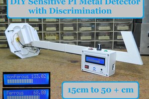
Pulse Induction (PI) metal detector operates on a principle based on sending short pulses of electrical current through a coil to create a magnetic field. This pulse lasts for a very short period, usually microseconds. When the pulse is transmitted, the magnetic field spreads outward from the coil. If there is a metal object near the coil, it disrupts this magnetic field. The coil then detects the change in the magnetic field caused by the metal object, and that results in a reflected pulse which is different from the normal pulse.
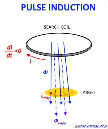
This difference is processed and emitted in the form of a sound or short beeps, with a frequency that changes depending on the distance and dimensions of the detected metal object. In several of my previous videos , I presented ways to make such a metal detector, including one very similar, with an Arduino Nano microcontroller. This time the device uses a more powerful ESP32 microcontroller board that also contains built-in Bluetooth, so now the construction is even simpler.
The creator of the original project is Neco Desarrollo and you can find other great projects on the given page. His idea of symbiosis between a microcontroller and a Smartphone is ingenious. The microcontroller easily accepts and transmits signals from an external electronic circuit, and the smartphone is a powerful tool for processing, as well as audiovisual presentation of the results.
This project is sponsored by PCBWay. This year, PCBWayis organizing the 11th badge design contest from March 3rd to April 31st. Follow the design requirements and Submit your designs in one of the given ways, and become the winner of one of the valuable prizes in cash and cupons. This contest is more than a competition—it’s a celebration of 11 years of innovation and a chance to dream about the boundless possibilities ahead with PCBWay.

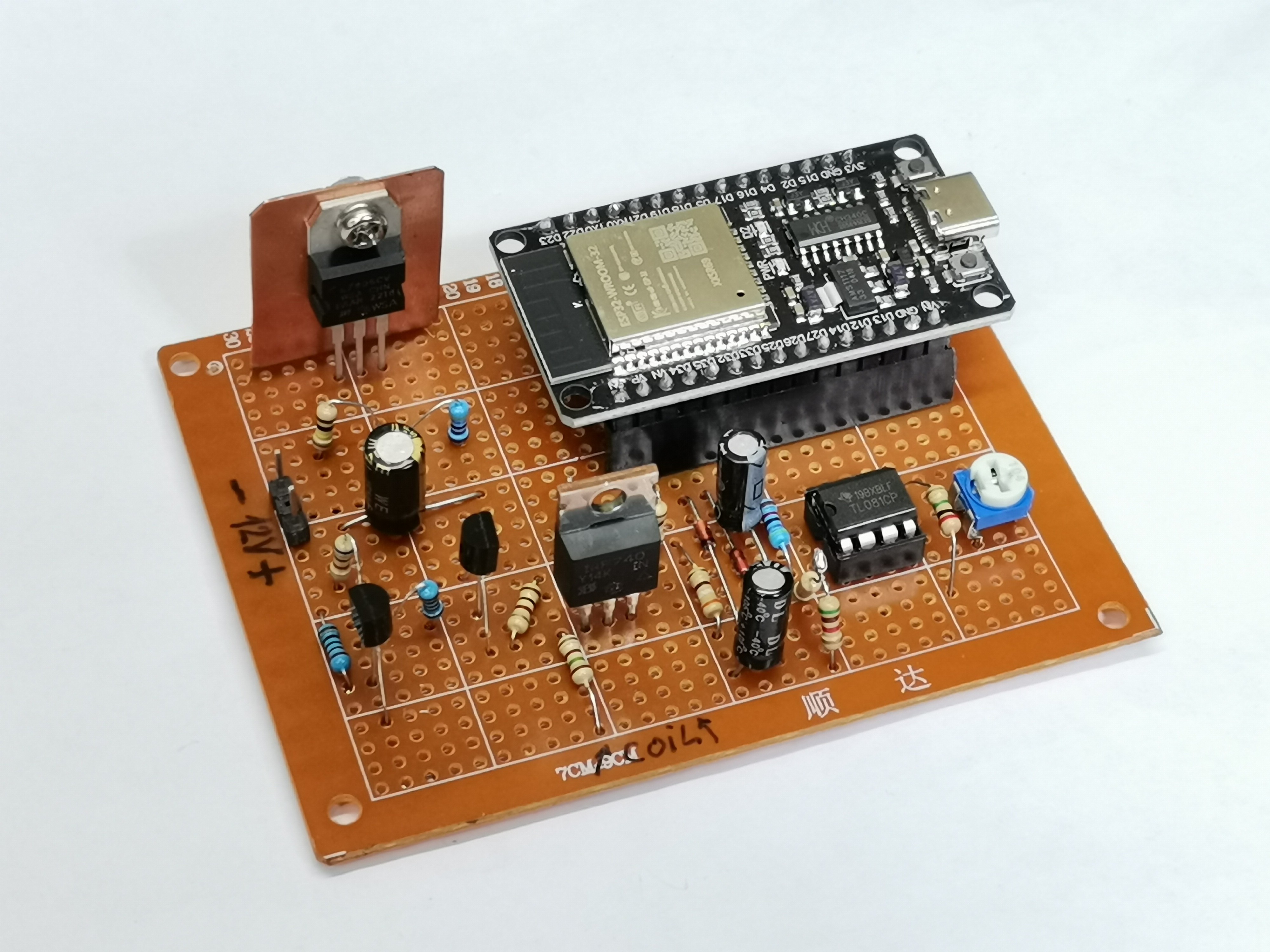
The input circuit is almost identical in all PI metal detectors and consists of the following components:
- A search coil consisting of 20 turns of insulated copper wire with a cross section of 0.4mm^2 , in the form of a circle with a diameter of 20cm.
- An operational amplifier IC, I specifically use the TL081, but the circuit worked almost identically with OP07, LM741, and CA3130 IC's.
- A power MOSFET with one or two driver transistors. In this case IRF740 , BC547 and BC557 but approximate replacements can be used
- A 7805 voltage stabilizer to power the microcontroller
- And several resistors, capacitors, and diodes.
To power the metal detector I use three lithium batteries connected in series, which is approximately 12V. The maximum total consumption is about 150mA.
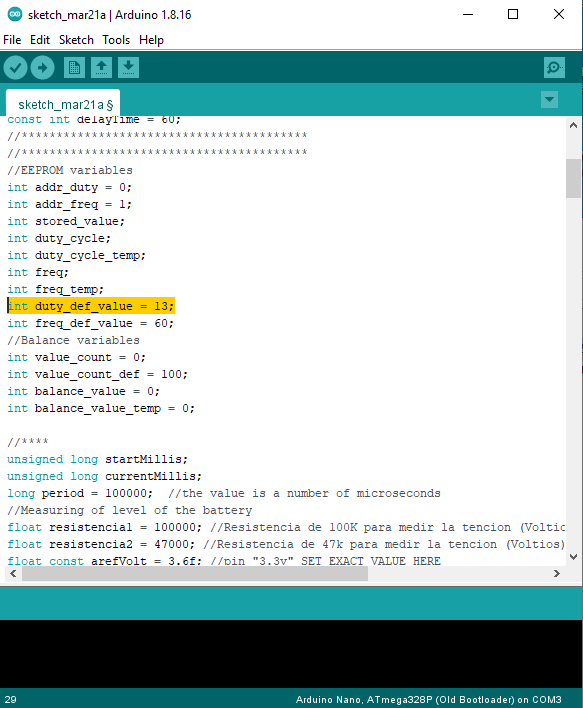
During the initial testing, I was unable to fully activate the Android application. The Bluetooth connection was established normally, but at the moment when I pressed the refresh button of the application, it disappeared from the screen, or an error appeared, depending on the version of the Android OS. Since the application is not mine and I normally do not have the conditions and knowledge for any modifications, I focused on modifying the input part with the microcontroller, or Arduino code. The changes consist of the following: I changed the order of the initial duty cycle value from 16 to 13, and the corrected line in the code looks like this:
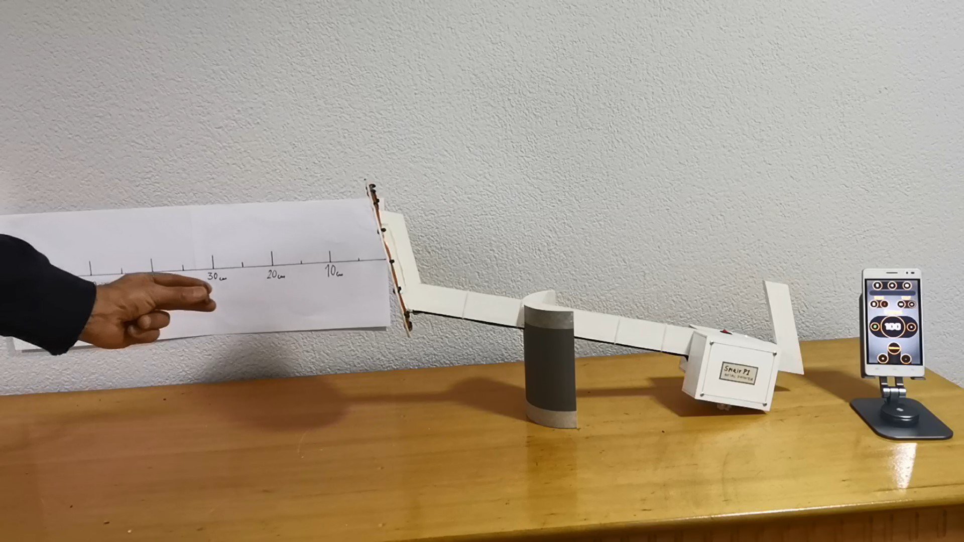
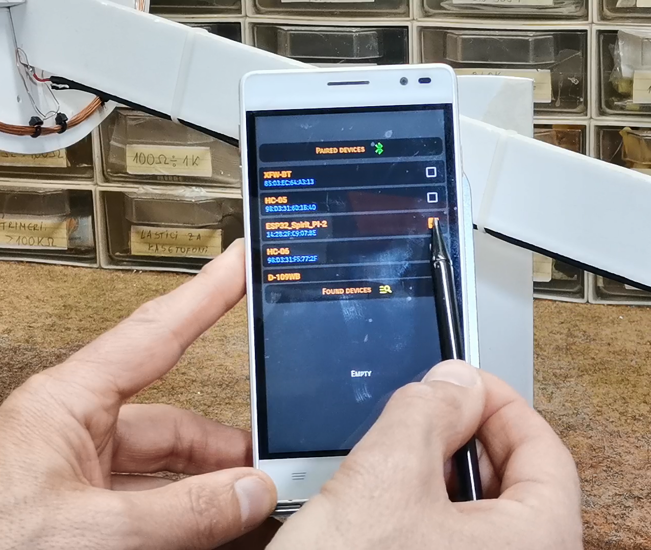
After this, the Android application will work normally and we can start testing. First, let me explain how the application works. After the first start, we go to setup and select the metal detector version Spirit PI. Then we go to Bluetooth settings and select ESP32-Spirit PI-2 and go back.
Now I press the refresh button and from this moment the device is ready to work. The interesting fact is that we can very easily change the values for the generated frequency and duty cycle, obtaining different performances depending on whether we want to detect massive or small metal objects.
Next, let's use an oscilloscope to trace the shape and changes of the signal...