Nick Sayer
This project draws inspiration from both my reset-o-matic and AC Timer projects.
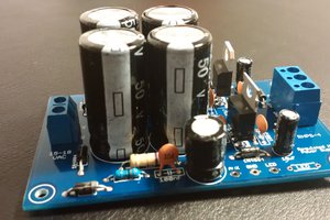
On the AC side, we have an isolated power supply, an opto-isolator driven triac switch, and power input and output jacks.
The isolated power supply is a bit overkill here, except that we do actually need some low-voltage circuitry to pull this off, and it needs to be isolated for safety.
The triac driver optoisolator presents us with an LED input. The anode gets a series resistor to the 5 volt supply. The cathode goes to an N channel MOSFET to switch it on and off. The MOSFET needs to default to the "on" state, so the gate has a pull-up resistor to the +5 supply.
The input is intended to pull the gate down to ground to turn it off. A DC blocking diode will protect the power supply from any stray voltage that might be applied to the input.
An LED and its series resistor are in parallel with the relay diode to give a visual indication of what's going on.
The AC side of the triac circuit starts with a BTA-20 power triac. Given sufficient heat-sinking it's capable of switching 20A, but we're not going to ask quite that much. In parallel with the triac is a snubber circuit to reduce the impact of potentially inductive loads at turn-on/turn-off. The BTA-20 is supposed to be insensitive to that sort of thing, but it shouldn't have to go it alone without any support. The triac will turn on for a half-cycle whenever its gate is pulled towards the T1 terminal (it's important to note that the T1 and T2 pins of a triac are not interchangeable because of the gate biasing requirement). So essentially the circuit can be thought of in two states: If it's off, then neither the 3020 nor the triac will conduct. So there will be a relatively high voltage across them, but no current flow (beyond a tiny leakage current). If it's on, then both will conduct, which essentially means there will be no voltage (beyond a tiny drop) across the entire circuit for most of the cycle. At the zero-crossing, the triac will turn off, so a voltage will start to build up until the gate reaches the trigger voltage, which is only about 2 volts. Because of all of this, the biasing resistors don't have to be particularly beefy. The snubber components don't either, because they only see fast spikes occasionally. The capacitor, however, does need to be able to hold back the full AC peak voltage (about ±170V) when the triac is off.
The input is a 2.5mm tip-sleeve jack. The sleeve is ground and the tip is the input. If you short the two together, then the cathode of the DC blocking diode will be forward-biased from the gate pull-down resistor and the gate of the MOSFET will be turned off. With the input at high impedance, the pull-up resistor will raise the gate, turning the MOSFET on. That will power both the indicator LED and the opto-isolator input.
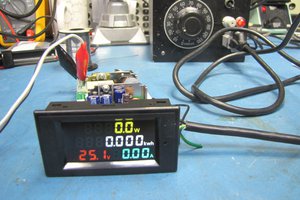
A Mac Studio has a maximum power draw of 480 watts (a Mac Pro would require nearly 1.3kW, but nobody buys those). A Mac Mini or iMac will draw much less. That's 4A at 120V. So our design spec is for 5 amps. A BTA-20 triac will dissipate 5 watts when passing 5A. The maximum junction temperature is 125ºC and the expected ambient temperature is 20ºC. That gives us 105ºC of temperature rise we can tolerate. The junction-to-case for AC is 2.1ºC/W, so 10.5ºC, leaving 94.5ºC. That means our worst acceptable heat sink should have a thermal resistance no worse than 18ºC/W. Fortunately, that can be accomplished with a minimal heat sink, but it will require the case to have some ventilation slots to be designed in.

 Mario Ninic
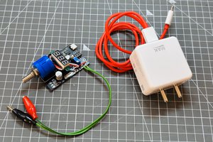
 Lithium ION
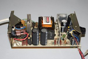
 Keith
Keith