 William Oprey
First thing on the agenda: Batteries. Obviously, a handheld console that only works when plugged in would be pointless, so we need a portable power source. Luckily, we can do what everyone else does, and use a LiPo.
LiPo batteries have a few caveats in use. For one, they come in discrete cells, with each cell having a voltage varying from 3-4 V. If a cell is discharged to under 3V, it becomes internally damaged and cannot be used anymore, and if a cell is charged significantly past 4V, they tend to explode, which is not good for you, or anyone in your immediate surrounds. If multiple cells are used, they also have to balanced while charging, or you guessed it, they explode.

Luckily, basically every consumer device ever is powered by one of these things, and since last time I checked we are all still alive, we've gotten pretty damn good at using them. Practically, this means there are plenty of off the shelf BMIC (Battery Management Integrated Circuit) modules that provide all functions required to safely charge and use a LiPo battery, with some drawbacks. Because this project will be extremely space constrained, in its final form, I have no choice but to integrate the charge and power supply modules into the final "mainboard" PCB, meaning no cheating using a PiJuice module, or similar hats. Because I'm not made of money, I have, and will be prototyping these module on a separate PCB, before integration into the final product.
The saying "Move fast and break things" has been stolen and heavily misused by business types lately, however in prototyping, the saying remains very literal. Since I'm using TI charge modules, I can just rip off their example circuit layouts with little consequence, however component selection is a different matter, and when you forget that Amperage ratings exist for a reason, bad things happen:
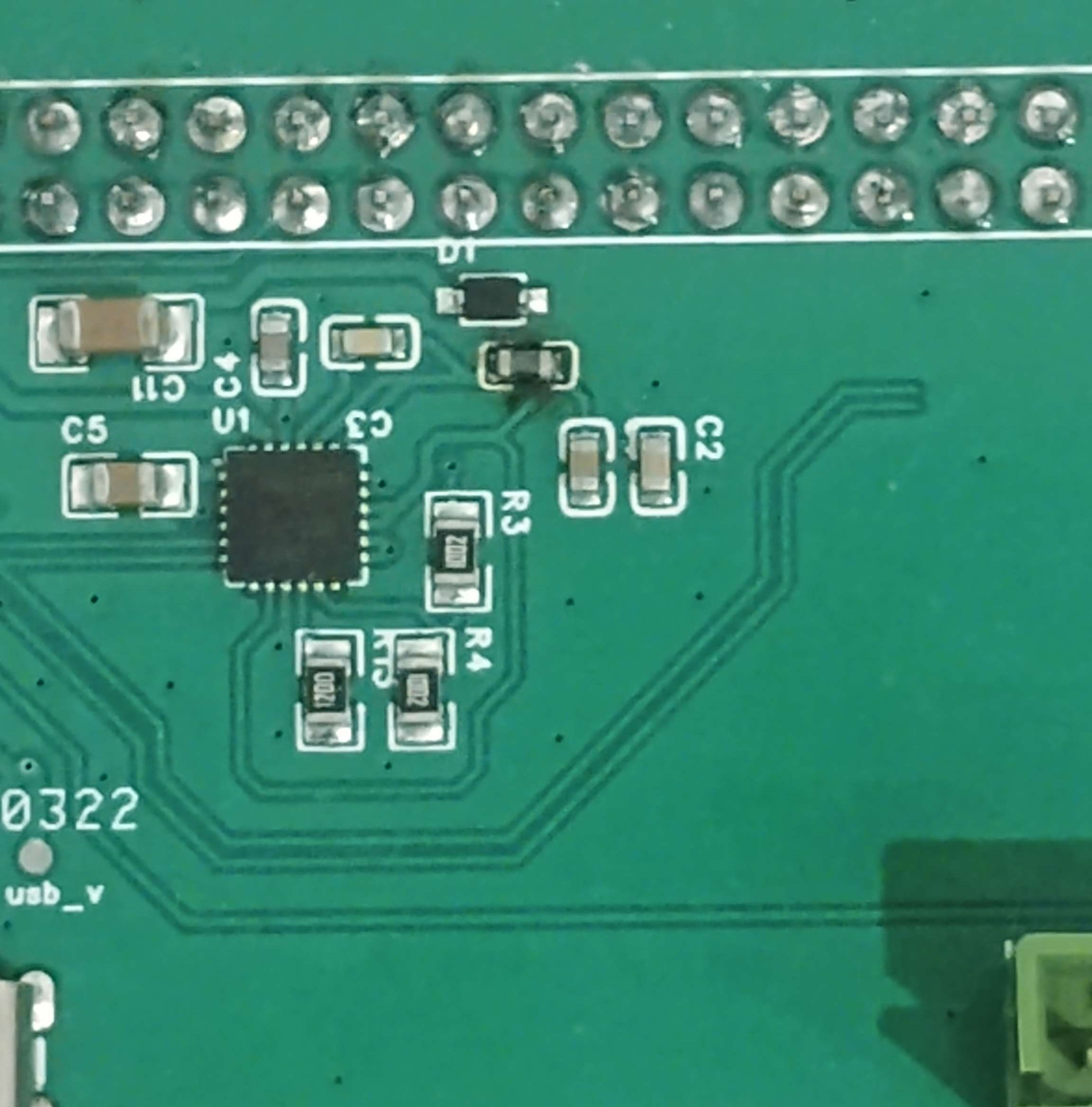
One burnt inductor later, back to the drawing board. What I neglected to realise is that the BMIC I'm using, the BQ25895, features an integrated buck boost voltage converter. This operates at the full supply amperage of the load, meaning a real beefy inductor is required to avoid "rapid thermal failure". Buck converter design also has a few other caveats, that I had neglected, as they require quite large traces, to avoid impedance issues, while also requiring a minimal loop area between the inductor and BMIC, for EMI reasons. One redesign later, and I had a (mostly) working board:
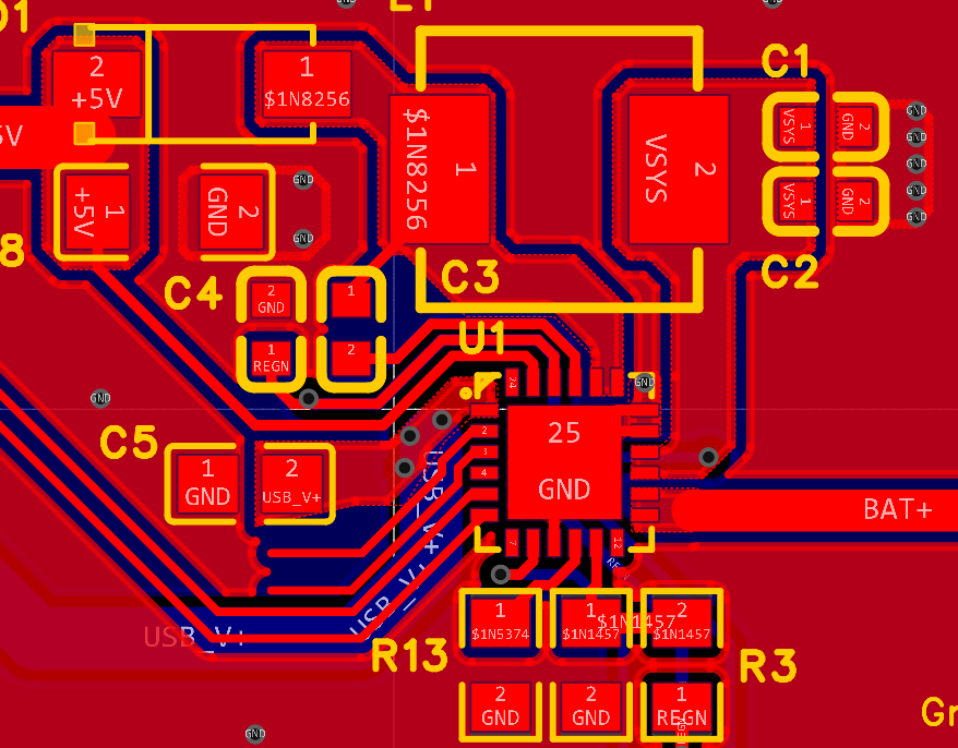
A more competent buck design, note the small current loop and full ground plane
Testing the resulting boards, the best I can say is that they almost work. While battery charging works perfectly, the BMIC I'm using has given me some "unique" issues. As the IC has to not only buck any input power down from 5v to 4v while charging, but also boost the battery output from 4v to 5v while supplying, the onboard switching regulator must switch between buck and boost function, depending on the voltage input. This cannot be done instantly, requiring a 40ms delay, which unfortunately is enough time for the Pi to run out of power and die. In practical terms, this means every time the Pi is taken off charge, it shuts down, something that gets very annoying very fast.
The other issue I'm facing is much less technical, and much more idiotic. Turns out that when plugged in, the BMIC bypasses the regulator and supplies the full system output through another separate pin, in this case a pin I basically ignored, and made 0.2mm thick. Obviously, pushing 3A though 0.2mm of width causes problems fast, and in my case the resulting voltage drop is enough to immediately shut down the Pi, meaning the thing won't work on charge either.
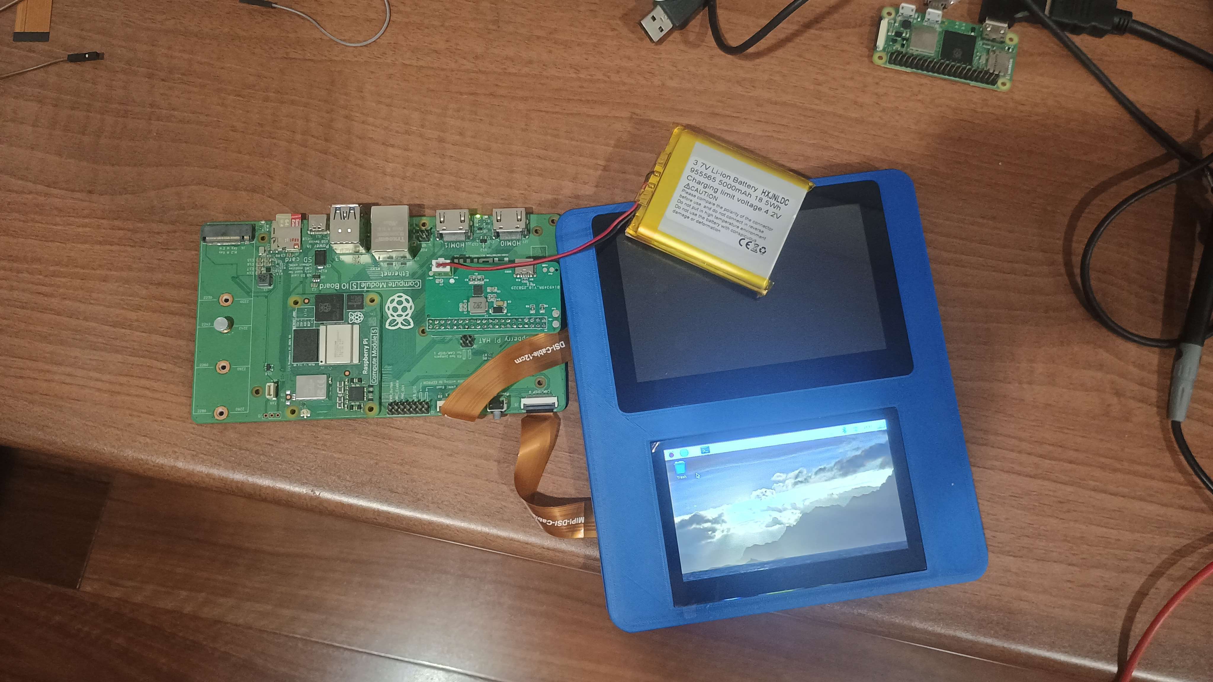
So, much work to be done, but on the upside, the Pi is portable now (With massive, impossible to ignore issues)
Next steps include sticky taping an external buck converter to the board, to hopefully fix those dropout issues, and actually reading datasheets next time like a real engineer.
Discussions
Become a Hackaday.io Member
Create an account to leave a comment. Already have an account? Log In.