 Cees Meijer
 Soldering the wires directly to the switches, so close to the PLA frame is a challenge. The plastic tends to melt rapidly when a soldering iron approaches. But its possible and little melting it not too bad. For the wiring itself I followed this schematic:
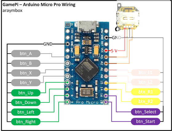
Well, more or less. It actually does not matter that much which switch is where, since each switch is assigned a specific function at the first start of the RetroPie software. And there is no analog joystick as shown here connected to A2 and A3.
How the power is wired:
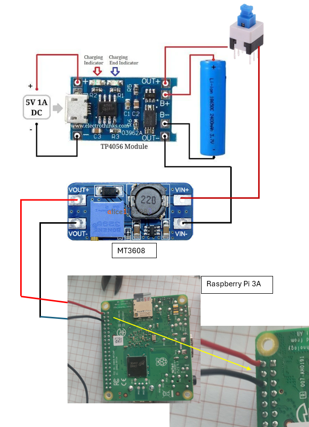
The Battery is connected to the TP4056 charger. From there the battery voltage (3.7V) is routed through the switch to the MT3608 voltage converter which is set to exactly 5 VDC output. This voltage is applied directly to pin 2 and 6 of the Raspberry Pi GPIO header.
And so we can test the final circuit. It works!

Discussions
Become a Hackaday.io Member
Create an account to leave a comment. Already have an account? Log In.