First Year Honors Project
My completed first year honors project at the University of Arizona
My completed first year honors project at the University of Arizona
To make the experience fit your profile, pick a username and tell us what interests you.
We found and based on your interests.
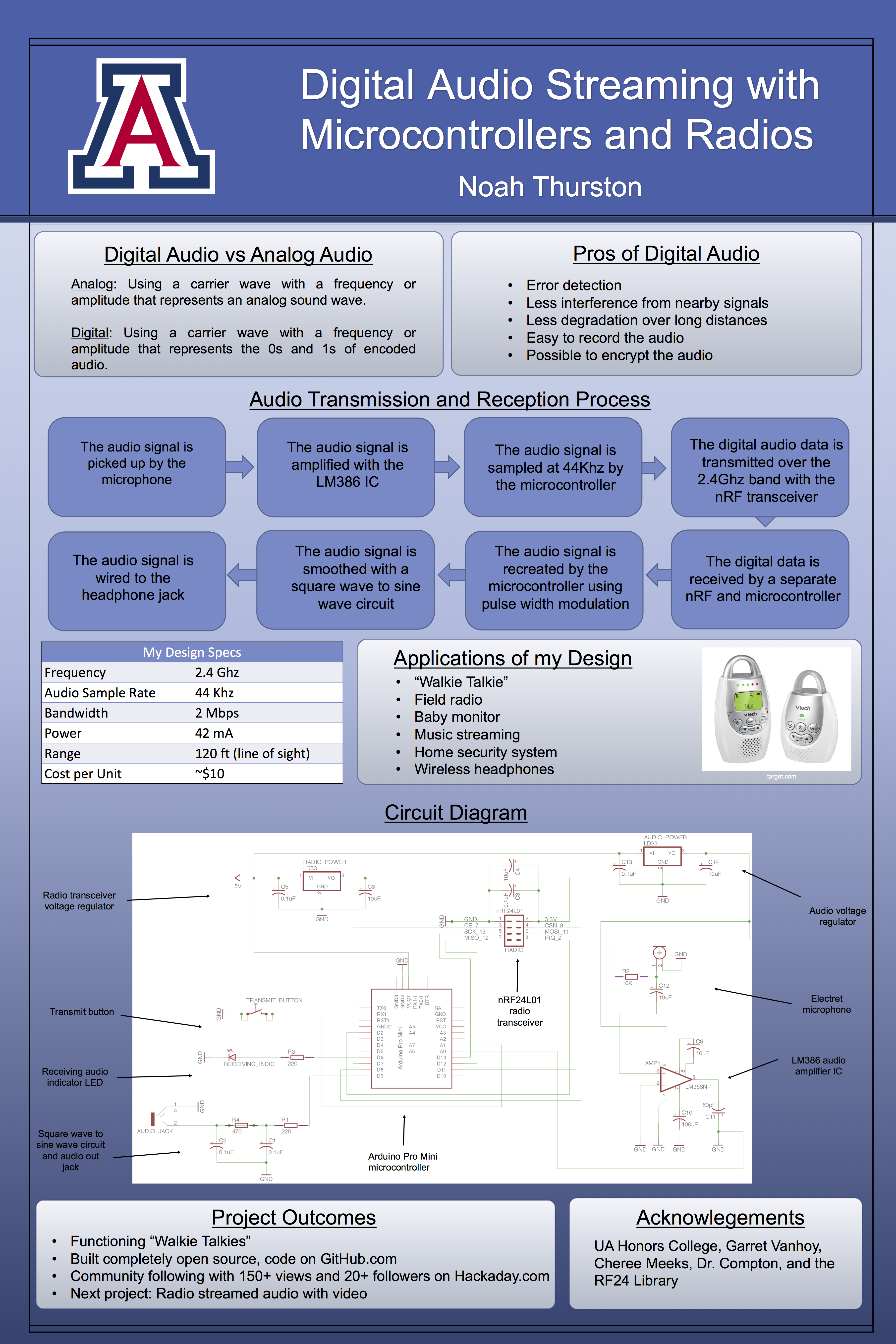
This is my last post for this project, as I will be presenting my project findings and demonstrating my design tomorrow. The design for my poster board is attached below.
The code for the radio is uploaded to my GitHub at https://github.com/noahthurston/honors_project so that others can use it for their own projects, and the schematic for my design is in the last post for those that want to create their own or use it as a basis for their own design.
I hope others continue to add to projects like these, I think it would be especially cool to see a video branch of the RF24 library. This is something that I am considering writing in the future, so stay tuned for that. Also, a special thanks to TMRh20 for his great RF24 Audio library, as well as to the UA Honors College, Garret Vanhoy, Cheree Meeks and Dr. Compton for also helping me with this project.

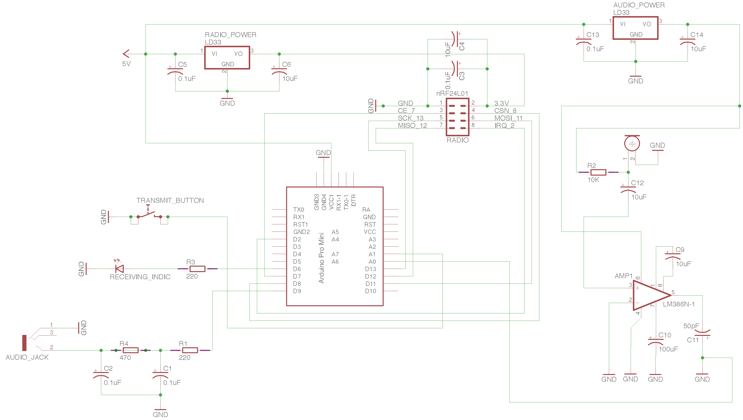
Below is the schematic for the final design of the radios. Each one features an arduino pro mini for processsing, an nRF24L01 transceiver, a LM386 audio amplifier, an electret mic, two LM1117 3.3V voltage regulators (one for nRF power and one for audio power). I decided not to use the analog switch because the output from the arduino did not need to be amplified when it is just going to earbuds. This allowed me to cut out the need for the switch.
 I also soldered one radio onto a protoboard for my presentation, the pictures of which are below. The potentiometer is the volume control dial for incoming audio, the LED below it is an indicator for the incoming audio, the pushbutton is to "push-to-talk" and the electret mic below it is for picking up the audio for transmission. And the final PCB sticking out the top shows the trace antenna, and since the module is placed into a 2x4 set of female headers, any nRF24 module can be used, including one with a real antenna.
Since most of the work needed for the radio and microcontroller side of this project is done, I've been working mostly on audio side. This includes designing the circuits that allow audio to be input from a mic and output from a speaker. This seems pretty easy, but has proven to be quite difficult because each audio stream must be amplified before being sent to the arduino for transmission or to the speaker for output.
I've already been able to use a LM386 audio amplifier to amplify audio, but now I want it to be able to handle audio from two separate sources (microphone and arduino) and send it to two separate places (speaker or arduino). I considered just closing these two circuits together so that both the microphone and the arduino audio were always being amplified and the output was always going to both the speaker and the arduino, but this was proven to be a terrible idea. When the circuit is built like this what is picked up by the mic gets amplified and put out by the speaker, which then gets picked up by the mic again, creating terrible back feed. And when the audio that was received by a user gets amplified, it ends up going to the arduino to be transmitted back to the source as well as being output to the intended user.
To stop this from happening I decided a needed some sort of switch in series with each of the four audio connections; mic to amp, arduino to amp, amp to to arduino and amp to speaker. At first I tried some NPN transistors, with the the emitter and collector in series with the each path, and the base being controlled by the arduino, but this didn't work at all. The base had to be powered by an arduino IO pin to close the circuit, which I think added voltage to the audio voltage, distorting it. Plus the arduino voltage was also probably oscillating slightly due to power hum, so this probably further distorted the audio quality.
After some research, I found this stack exchange thread (http://electronics.stackexchange.com/questions/66332/mosfets-or-bjts-for-using-as-switch-for-audio-signals) which mentions using analog switches for switching audio signals. And with a search of online of Elliot's Electronics inventory I was able to find the NTE7110, a 3 channel analog switch in a 16 pin DIP package. This chip looked especially good since the datasheet said it was "designed to be used as an electronic switch in VCR and audio signal processing applications." I got my roommate to drive me down to Elliot's so I could pick up a few (thanks Mike) and after some trial and error these seemed to work as I liked. The chip's data sheet can be found here (http://www.nteinc.com/specs/7100to7199/pdf/nte7110.pdf), but as you can see it isn't much help in describing how to use the chip. Luckily I was able to figure out how to use it with just some tests with LEDs. Basically there are three channels, and each channel has two inputs, A and B, an output, and a control pin. By having the control pin pulled low to ground, current can flow from input A to output. By having the control pin pulled high to 5V, current can flow from input B to output. Using this chip I was able to control the four channels with just one pin. Below is the schematic I made in Eagle Cad to show how I'm going to wire it in the audio circuit.
For audio transmission, audio needs to be taken from the mic, amplified, and then sent to the arduino, so the control pin should be should be low, which allows all A inputs to go to their respective outputs while blocking all B inputs. For audio reception, audio needs to be taken from the arduino, amplified,
and then sent to the speaker, so the control pin should be should be high, which allows all B inputs to go to their respective outputs while blocking all A inputs.
Next I plan on wiring together the full audio circuit with this chip, the mic, and the amp, and then making a schematic for it.
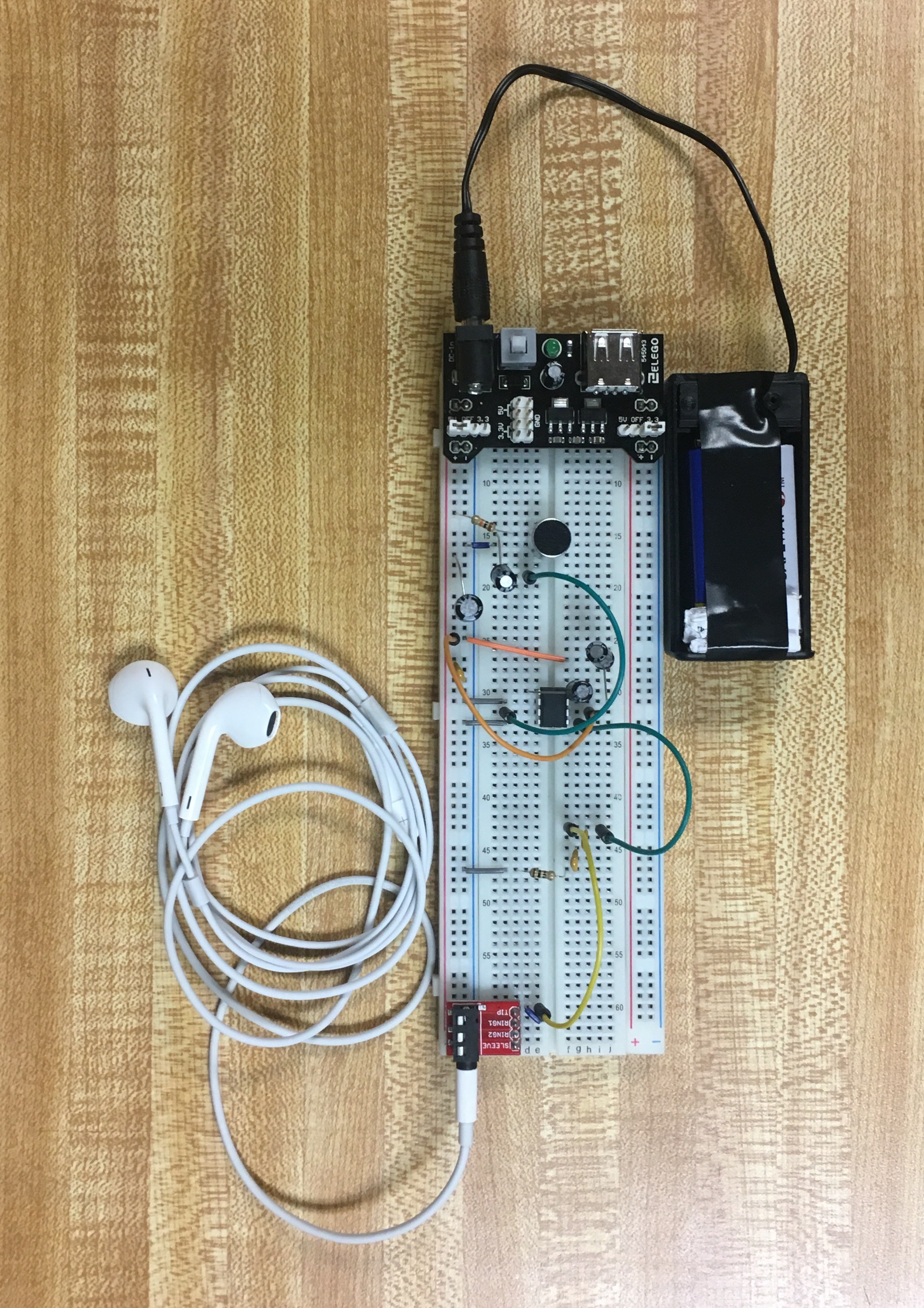
Recently I've been working on the audio side of the project. This includes making a working microphone for audio input and a speaker for audio output. After receiving some electret microphones, low power speakers, and LM386 low voltage audio amplifiers I started to build a simple circuit to see if I could get the microphones to work. This meant wiring an electret microphone to an LM386 amplifier, and then wiring the Vout to a 3.5mm audio jack so I could hear what the audio quality is like without worrying about back feed. A picture of the breadboarded circuit is below:

The trickiest part about building this circuit was wiring the 8 pin LM386, but the TI datasheet for it was a lot of help as well as this blog (https://lowvoltage.wordpress.com/2011/05/15/lm386-mic-amp/) which went into some detail explaining the possible audio gain this chip can supply.
In the top of the picture is a power supply board that attaches to both sides power rails, then below that is a electret microphone. These microphones aren't super high quality, but they are dirt cheap ($0.30 a piece) and will do for the audio quality that we're going aiming for. Any nicer of a mic would be waste considering our wireless bandwidth is limiting the audio quality anyway since we'll be sampling 8-bit audio at only 24kHz.
From the electret mic the voltage goes to the input pin (pin 3) of the LM386 audio amplifier. This amplifier defaults to 20 gain, but can be set to 200 gain by adding a 10uF capacitor connecting pin 1 to pin 8. Also on the LM386, two pins are grounded and another is powered. Then the output voltage can be sent to the analog in of an arduino, or in this case the headphones. When I first built this circuit without the amplifier the mic was too quiet to hear, but with the LM386 set to 20 gain it was pretty loud, and then when it was set to 200 gain it was very loud.
The sound quality continued to be good until I wired it to the arduino and nRF circuit for transmission (that circuit isn't pictured here but it will be shown in a later post). When the power supplied to the arduino was also used for the microphone, there was a steady hum in the background of the microphone audio output. At first I thought this could be filtered out with some bypass capacitors, but nothing seemed to stop it. After some googling I found out this hum was most likely due to the arduino and/or the nRF oscillating the power source voltage as it drew from it. More capacitors near the LM33 voltage regulator still wasn't able to stop it. From many tests, adding and removing capacitors or different values in different places, it seems like those capacitors (usually ranging from 0.1uF to 100uF) are good enough to keep power steady so the microcontroller will have a robust power supply, but not good enough to filter all oscillations detectable by the human ear.
To stop this hum I added another LM33 that is powered by the battery pack and is the sole power source for the microphone. This stopped the power hum, but at the inevitable cost of more drawing more current from the batteries. I considering trying to make an audio filter, like the one in this schematic here http://www.electroschematics.com/5877/audio-noise-filter/ , but that seemed like a far more complicated and pricey solution. So for now I'm sticking with the extra voltage regulator.
With the power hum problem solved, I was able to transmit and receive audio from one arduino to the other with decent sound quality using the simple getting started RF24 Audio sketch. Next I want to modify the circuit to use the LM386 for both microphone amplification and speaker amplification, since each device will be both transmitting and receiving. This will also mean writing code to allow users to "push-to-talk," as well as allowing them to possibly change channels and multicast.
As of about two weeks ago, I've had some basic tests for nRF24L01 and the Arduino pro mini completed.
The goals of this test: Be able to turn on and off two synced LEDs on two separate microcontrollers with the press of one button.
This involved:
Below is one of the two devices made for this test (the other one is built with the same design on a bigger breadboard)
The main part of this circuit is the Arduino pro mini shown in the center. I chose this microcontroller because it was well supported by the RF24 library and very cheap (~$3 a piece). I wrote the code for it with the RF24 "getting_started" sketch as reference, and you can find both on my linked GitHub repo.
Towards the bottom of the breadboard you can see the black nRF24L01 module, with the small trace antenna. I chose these modules because they are also very, very cheap (~$1 a piece), relatively low power since they draw about 20mA at 3.3V and easy to interface over an SPI bus. You can see attached to this modules on the DIP pins are two capacitors; a 0.1uF ceramic disc capacitor and a 10uF electrolytic capacitor. These are attached parallel to Vcc and ground to act as bypass resistors and smooth the power supply for the nRFs, who are known to have faulty performance without a good power supply.
Also shown is the lit LED on the top right and black pushbutton on the bottom right. The button is connected to an arduino io pin, and is normally open with a pull down resistor to keep the state from floating. The LED is also connected to an arduino io pin.
Finally in the top left is a 3.3V regulator, and to the left is a battery pack. There is a lot to talk about when it comes to powering this project, and I plan on doing a separate build log on power alone, so I'm going to be brief here. The battery pack contains 3 AAA batteries for a 4.5V supply. The arduino should be supplied 5V but, it seems like 4.5V is within its tolerance for something this lower power. And since the arduino has an on board power regulator, I was able to connect the battery pack leads directly to the arduino Vcc and GND. The 3.3V regulator at the top is a LM33, part of the 1117 series, and is for the nRF. It has a dropout voltage of 1.2V which means for it to produce a Vout of 3.3V the Vin must be +4.5V, so this AAA battery pack is just barely cutting it, but regardless it still seems to be working.
(a video of the working devices can be found on the linked GitHub in the "pictures-videos" directory)
After debugging the code a little bit, everything worked well. When the button was pushed on one, both LEDs lit up immediately with no perceivable lag. The range, when the PA level was set to the highest possible was upwards of 40 meters in open air but it struggled to get through any barrier thicker than a couple inches. Ultimately the test was a success; my code and the library worked on the arduino, the nRF was responsive when transmitting and receiving, and the battery pack power was enough for both the microcontroller and the arduino.
Create an account to leave a comment. Already have an account? Log In.
Become a member to follow this project and never miss any updates