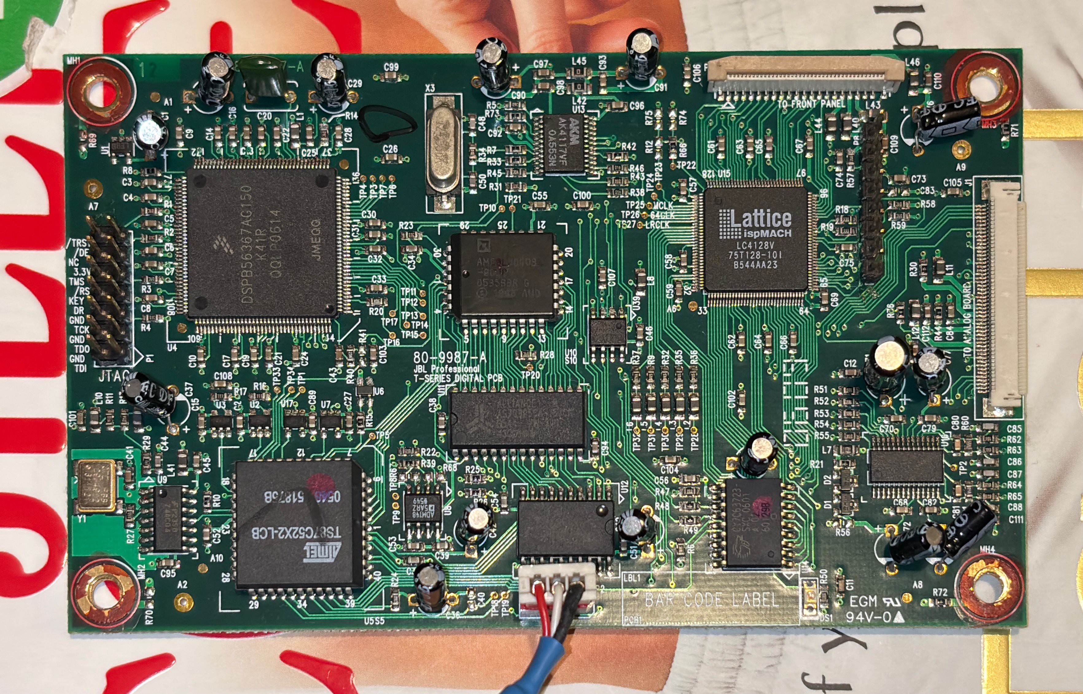
With the broken speaker torn apart, first order of business was to check both PCBs for popped capacitors or any other evidence of component destruction. There were no obvious signs of component failure, but I was pleased to find a number of very handy features on both PCBs - power LEDs for each supply rail of the PSU on the analog board, and two 0.1" headers on the digital board, one with JTAG pins labelled!
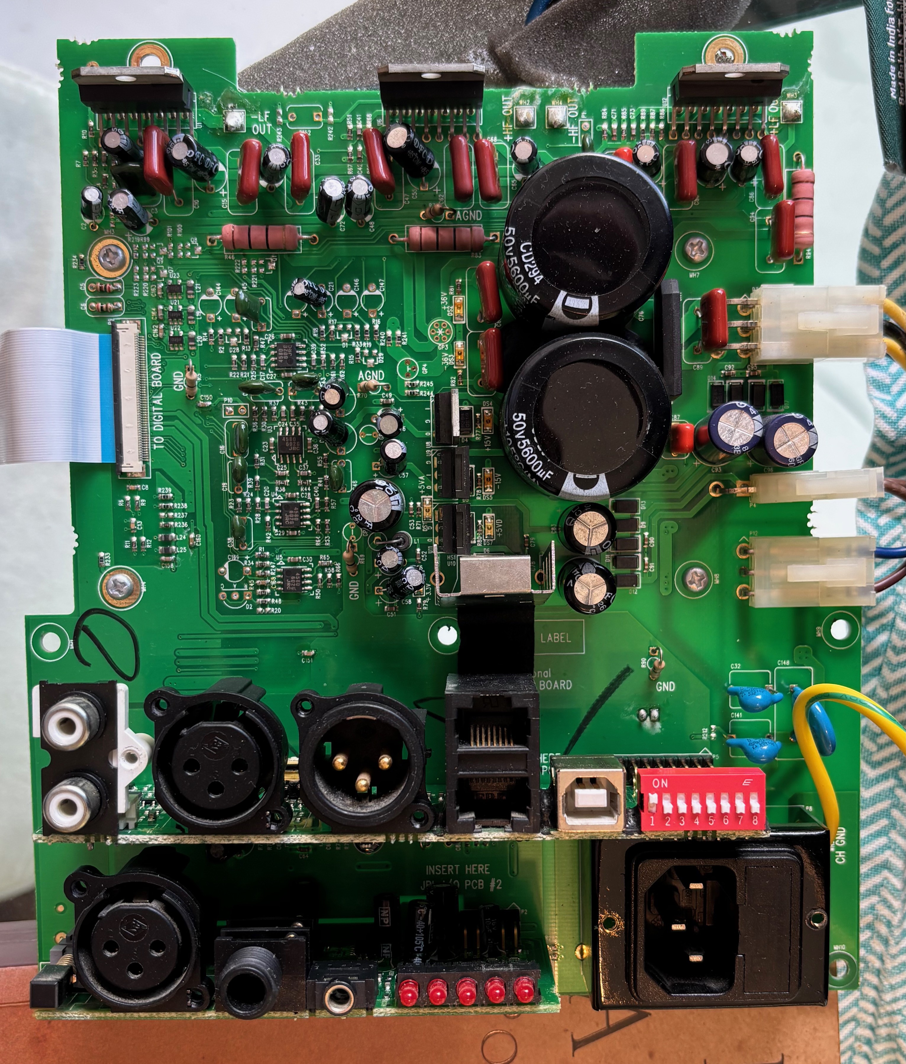
Everything looked normal checking the rail voltages, so my suspicion turned from the PSU section to either the digital board or the control board (with the buttons and LEDs) up front. The most obvious step seemed to be to swap the digital board from the working speaker into the broken speaker. If this brought the broken speaker to life, the failure was almost certainly in the digital board. It felt a little risky, as I couldn't be sure that there wasn't some fault with the analog board that had fried the original digital board and would fry the working one when I swapped it in. After checking the voltage at the V+ input on all the chips that I could identify, I couldn't find an obvious fault so I decided to pull the trigger.
Thankfully, the broken speaker did not fry the working digital board. And with the swap, it worked! So the fault (presumably) had to be somewhere in the original digital board. This was both good and bad. Good, because digital stuff is fun, and the architecture was pretty old school - 8-bit MCU, discrete flash, discrete SRAM - so I was fairly confident I could reverse engineer quite a bit by following the traces and probing signals with my basic USB logic analyzer. It was also bad, because if the issue was corrupted flash memoery or a dead chip, I wasn't sure I'd be able to recover the original programming or program a new replacement part. However, the JTAG header, relatively simple architecture, and having a known working board gave me hope.
Discussions
Become a Hackaday.io Member
Create an account to leave a comment. Already have an account? Log In.