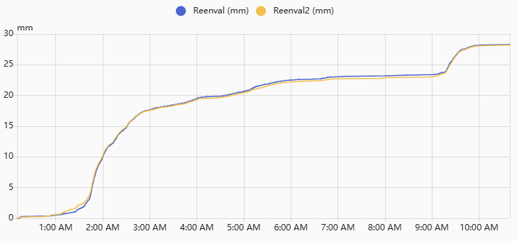
Johan
While making a tipping bucket rain gauge is in principle fairly straightforward, making it robust and durable yet sensitive is not, as we learned the hard way. Others have even more experience, especially regarding durability during deployment, and we found their musings most helpful while iterating our own design.
The Challenge
Due to its exposed position, a rain gauge must resist multiple simultaneous environmental onslaughts:
- The sun beats down mercilessly on an exposed rain gauge. And it has to be exposed, to do its job. Two main solar mechanisms conspire to limit its lifetime:
- UV - ultraviolet radiation breaks down molecular bonds, often leading to embrittlement of especially plastics, even ones supposedly UV-resistant. Living at altitude, as we do, aggravates this, but nonetheless we desire many years of trouble-free operation, not mere months.
- Heat - can stress electronics, lead to warping and binding of the mechanism, or leakage of water into areas where it should not go.
- Arthropods - insects and arachnids, to be specific: both ants and spiders have been found in previous versions. Especially spiders would move in and affix the moving seesaw to the base with their silky creations during the dry months, thereby disabling the gauge completely.
- Vertebrates - birds poo everywhere, and may even consider nesting in the funnel, although we have not yet run into the latter problem. At least we never had problems with snakes, as in the link above.
- Leaves and other wind-borne debris, which can block or clog the funnel.
- Weather - in addition to the expected falling water (i.e. rain) around here we also get:
- Hail - the gauge should be able to resist at least medium-sized hailstones. That is in fact how we learned that a previous collecting funnel had become brittle due to UV: a short hailstorm, involving quite small hailstones, left it in tatters, despite it having spent less than a year outside. Most disappointing.
- Wind - the mounting should be sturdy enough to resist wind forces, and the wind should also not be able to enter via the funnel or the drainage holes and somehow affect the tipping mechanism.
- Lightning - often associated with rain around here, care must be taken that it does not lead to false triggers, or damage to electronics.
- I have no idea how to handle snow. We don't do that around here. Perhaps a deep funnel, with tall vertical walls, to capture and keep the snow until it gets around to melting?
- Moisture - well, rain is wet, yes, but when electricity and especially electronics are involved, care must be taken to ensure that never the twain shall meet. And corrosion of metal parts means that stainless steel is probably a good idea for things like fasteners and axles. The link in the first paragraph above mentions even aluminium funnels succumbing to corrosion under their (admittedly extreme) tropical conditions.
It took multiple iterations to address most of the challenges listed above, and no doubt more lessons will be learned along the way, but we are pleased to present our latest incarnation for public consumption at last.
The History
Since the heady days of Covid lockdowns we were monitoring our rainfall using a Misol-type tipping bucket rain gauge, harvested from a defunct weather station. It triggers a magnetic reed switch each time the tipping bucket toggles, so a D1 mini ESP board, running Tasmota counts these events and reports them on the wifi network using MQTT. With Home Assistant in charge this means that we can monitor our rainfall in real time and also make decisions based on this information; primarily whether to run or inhibit the irrigation system.
The Misol sensor is surprisingly stout, but its native resolution is a bit over 0.3 mm of rainfall per tip, which is an uncomfortable size, being neither here nor there for those of a decimal orientation. So we increased the catchment area by printing (in vase mode, oh goody!) an extension funnel, to reach an effective resolution of slightly less than 0.1 mm per tip.
Then, as mentioned above, we were reminded once again that UV is a killer. It breaks molecular bonds, and the supposedly UV-resistant but admittedly thin plastic funnel could only resist so much for so long. It embrittled within months, and then disintegrated at the merest caress of hail.
So we had to find a way to foil those fiendish funnel-fragmenting photons. Which was to foil the funnel, actually, to fend off the malevolent ionising quanta.
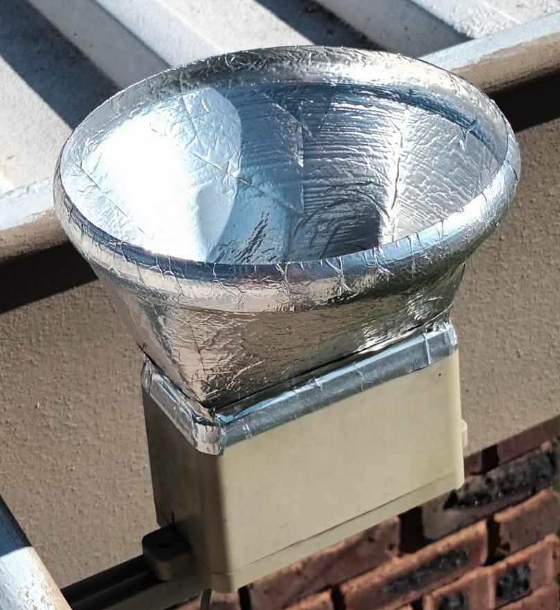
This foil cover seemed to do the trick. Several years later we are still going strong. (Strongly, actually. It is an adverb, after all.) It is the Misol unit itself which is now bearing the brunt, changing from light grey to a sickly beige under the relentless radiation and rain. Why we do not simply also cover it with the same adhesive aluminium foil is one of those baffling enigmas – it should be far easier to do than the funnel with its complex curves. But in addition to the visible degradation, it too garnered some internal infestations by opportunistic spiders, so apparently the time has come anyway to create a replacement, while it is still operational.
The Response
The trickiest part to get right is the tipping bucket – the main moving mechanism, preferably the only moving part. After many iterations we seem to have converged on dimensions quite similar to those used by the Misol. Could probably have saved a lot of time and filament had we simply started there, but where is the fun in that? And, like Mr Edison, now we also know what not to do. With moving parts often being prone to failure, the sensor itself is also solid state (a Hall effect sensor) instead of a reed switch with its moving electrical contacts. Those with traditional inclinations can probably still fit a reed switch in there if they prefer, though it may take a bit of carving to clear out a suitable mounting slot.
Throughout the mechanics various slots, lips, overlaps, bevels, and ridges all cooperate to ensure that water goes where it should, and not where it should not.
The base frame is designed with a definite wet side, where the tipping bucket mechanism lives, and a dry section, to protect the electronics. Made of extruded plastic (PETG, or perhaps ASA), as is almost everything else, the bulkhead between wet and dry is impervious to water, but quite pervious to magnetic fields, which is as it should be. Spooky action at a distance - magnets truly are magic.
In addition to the printed parts, we also used:
- A neodymium magnet. This design uses a 6mm round magnet, 2mm in thickness, but other sizes can also work - it simply has to be able to trigger the Hall sensor as it passes by, while not being too heavy; its weight is a not-insignificant fraction of the entire moving part.
- Stainless steel bolts: M4 x 12mm. You need 8 of those - two for the adjustable end stops, and six more (which can be shorter, say M4 x 8mm, if you prefer) to close everything up. Or they can be long too – it is just more work to screw them in.
- One stainless steel sewing pin, at least 26mm in length, to serve as the axle of the tipping mechanism. If it is too long you can simply snip off the sharp end after installation. In previous projects we proved the value of sewing pin axles under similar circumstances.
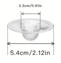
- An optional but highly desirable stainless steel drain strainer, ~5.4 cm in diameter, to keep leaves, branches, and bugs at bay.
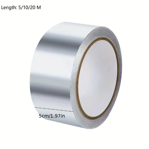
- Adhesive aluminium tape (search for “High-Temp Resistant Aluminum Foil Tape”). The width is unimportant, as you will do some complex patchwork with it anyway, to cover and protect the funnel both inside and out:
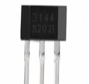
- A Hall effect sensor. We used a venerable A3144E Hall Effect Sensor, because it is digital (latching), cheap, and universally available (though supposedly obsolete). Or you could use some alternatives: A1120, US1881, A1104, MH182 - there is a plethora of similar sensors in the ultra-mini UA SIP package.
- Something to monitor the Hall effect sensor, and report on changes. We are pervasively Home Assistantified, therefore a small ESP-based wifi board running the redoubtable Tasmota code was our choice. The dry space should be ample – even a Sonoff Basic can fit in there. Or it can be left empty except for the sensor, as ours currently is, because, for now at least, it is monitored by the same unit servicing the old rain gauge, situated right next to it on the edge of the roof.
Printing
The printed parts are seven in total. Files can be found here: https://www.printables.com/model/1246110/files
- RainGaugeTipper – Printed at about 0.1mm layer height, with supports only in the cavities for the hub insert and the magnet.
- RainGaugeHub – Printed without supports, but with a brim, to improve bed adhesion.
- RainGaugeBottom – Printed without supports, with variable layer height. To facilitate easy assembly, an XY Size Compensation of -0.1 mm was used. This ensures that the top, the shield, the inner cover, and the screws can easily be fitted on, around, and in it respectively.
- RainGaugeInnerCover – No supports, and 0.3mm layer height. Variable layer height, actually, but because of its simplicity only the first and last layers are thinner.
- RainGaugeShield – As with the previous part, the variable layer height used mostly 0.3 mm. Supports are needed on the inner edge at the bottom, due to the horizontal step.
- RainGaugeTop – Printed without supports, except for the five mounting holes at the far end of the arm. You do not want or need supports in the thread for the funnel, or the grooves on the bottom face – it would be a nightmare to remove, and quite superfluous.
- RainGaugeFunnel – This one is printed in our beloved vase mode, at 0.2 mm layer height, with no top or bottom layers. Even though the nozzle is 0.4 mm wide, the extrusion width is set at 1 mm, to ensure a decent stiffness and strength. There are two sizes, with catchment diameters of approximately 125 mm and 150 mm respectively. You only need one.
We used PETG throughout – ASA should also work. The top and the shield was printed in white, which should hopefully reflect much of the sunlight, keeping temperatures in check, and possibly extending its lifetime. The funnel is white too, although it will be covered in adhesive metal foil anyway, so the colour is probably moot.
Assembly
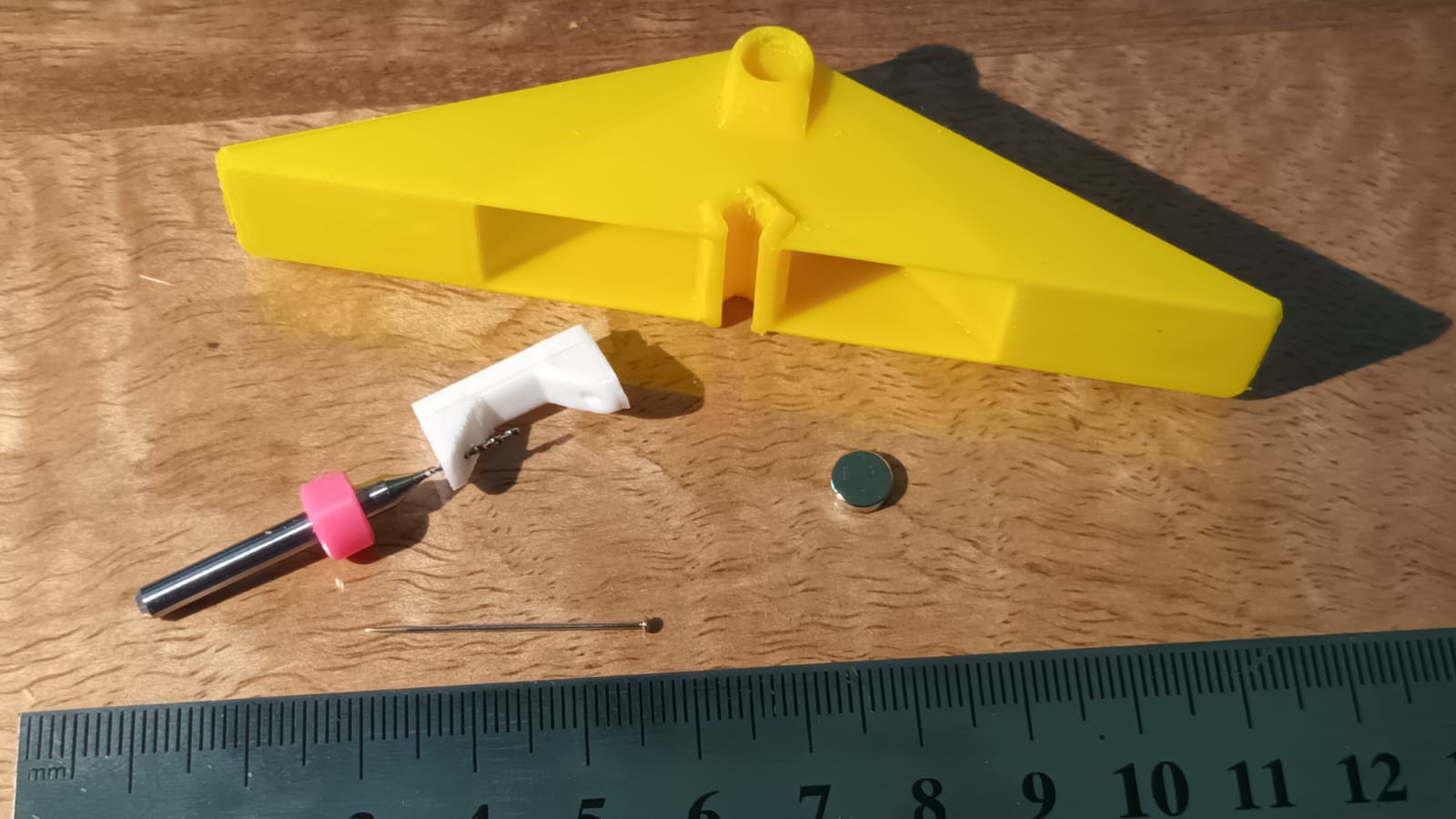
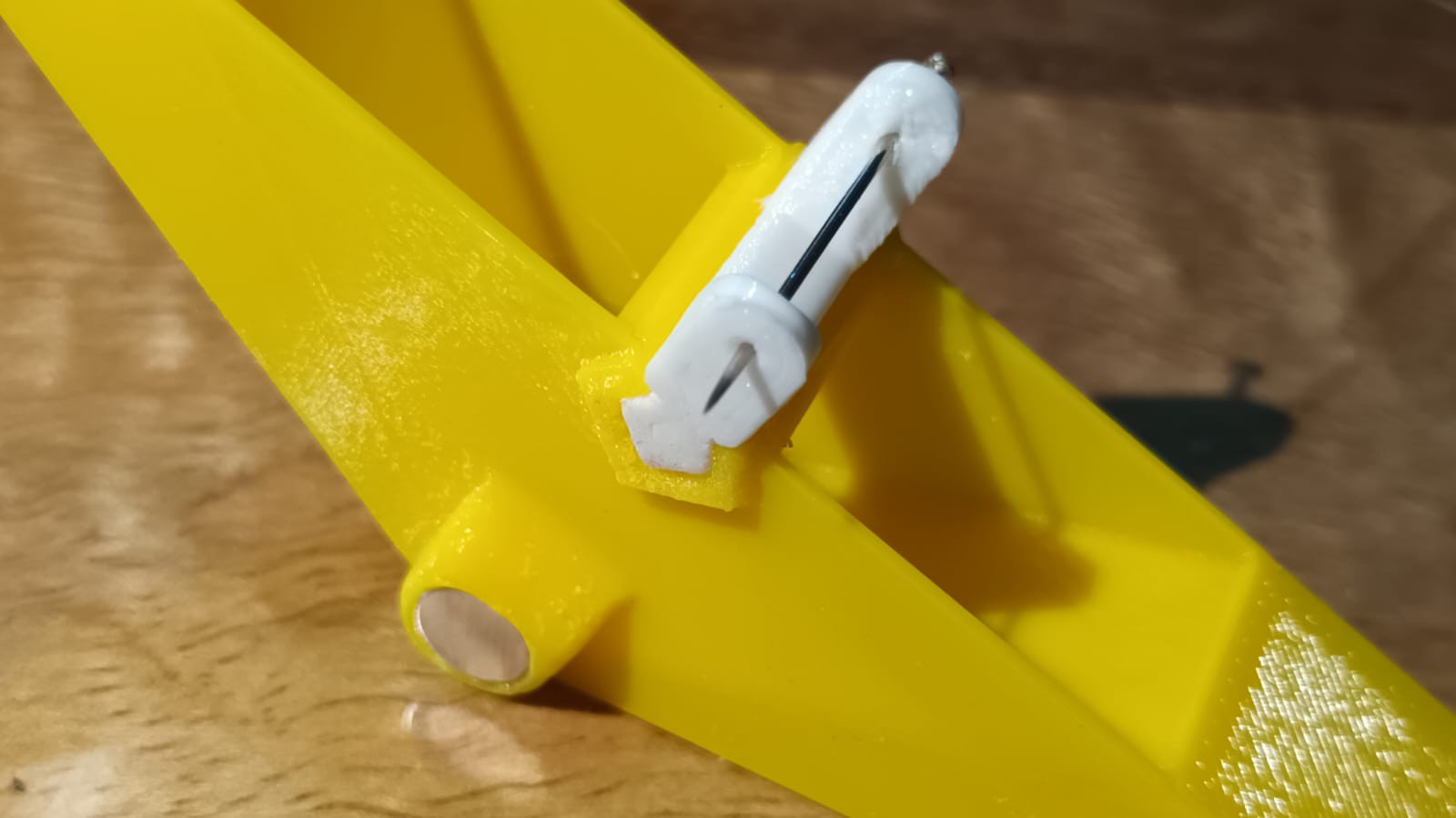
The 26 mm sewing pin axle is about 0.6 mm in diameter, hence a 0.8 mm drill is used to clean out the holes in the hub insert. A 1 mm drill will work too - all that matters is that the axle should move quite freely. The 6 x 2 mm magnet is pressed into its cavity (after removing the printing supports). Depending on the type of Hall sensor the magnet orientation/polarity may matter (it does with the one we used), so check before pressing it in - it is nigh-on impossible to remove without destroying the plastic part. It should fit tightly – if not, a drop of glue should do the trick. Similarly, the hub insert is pressed into the tipper, where it should stay. If it needs help, do what you should.

Mounting the tipping bucket mechanism in the bottom part is tricky. Really tricky. Clear the hole for the axle in the outside wall with the same small drill bit, then carefully manipulate the pin through this hole, through the holes in the hub insert, and all the way into the corresponding hole in the internal bulkhead. I did not ream the latter with the drill bit, to ensure a tight fit, even a seal. If the pin is longer than 26mm, it will protrude into the dry cavity; this is fine, but if it bothers you, simply snip off the end, flush with the surface. Just be sure to use a suitably sturdy side cutter – this is how you ruin delicate tools, if you are not careful. Or so I am told.
The moving mechanism should be exactly parallel to the internal walls of the wet cavity, with a small but definite clearance to each side. It must move quite freely, of course. Make sure no strings or wisps of filament in the cavity can affect its freedom of movement – one way would be to play a flame over all parts to shrivel away any such potential impediments. Insert two M4x12 bolts from the bottom through the threaded holes – they should fit fairly easily, especially if you printed it with the suggested -0.1 mm XY size compensation as you should have.
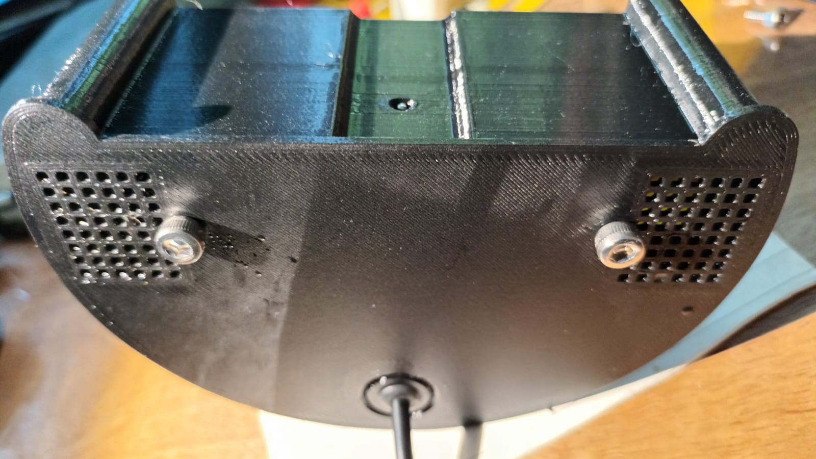
Adjust these two end stops so that the edge of the bucket ends up at an angle of about 8°, on both sides. The exact angle is not critical, but it is desirable to have it symmetrical, though even that will average out over multiple tips – we shall get to calibration later. If the angle is smaller (i.e. the tipping mechanism rests closer to the horizontal) it requires more water to tip it over.


The Hall effect sensor slides up into the slot, until it is visible through the inspection hole, which should place it directly opposite the magnet when the tipping mechanism passes through top dead centre on the other side of the bulkhead.
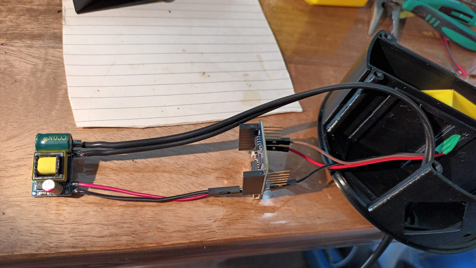


For testing and calibration we used a D1 mini board, with a lowly ESP8266 processor running Tasmota. This is powered by a mains-to-5V PSU, with the Hall effect sensor powered by 3.3V from the board, and its output line connected to an I/O line which triggers a counter. After ensuring that everything is communicating and happy, I isolated and bundled it up and slid the internal cover over it, to keep it snug and dry. The power line is fed through the hole at the bottom, which was lined with a rubber grommet. But a dollop of hot glue or silicone or similar sealant would serve equally well to keep out water and undesirables.
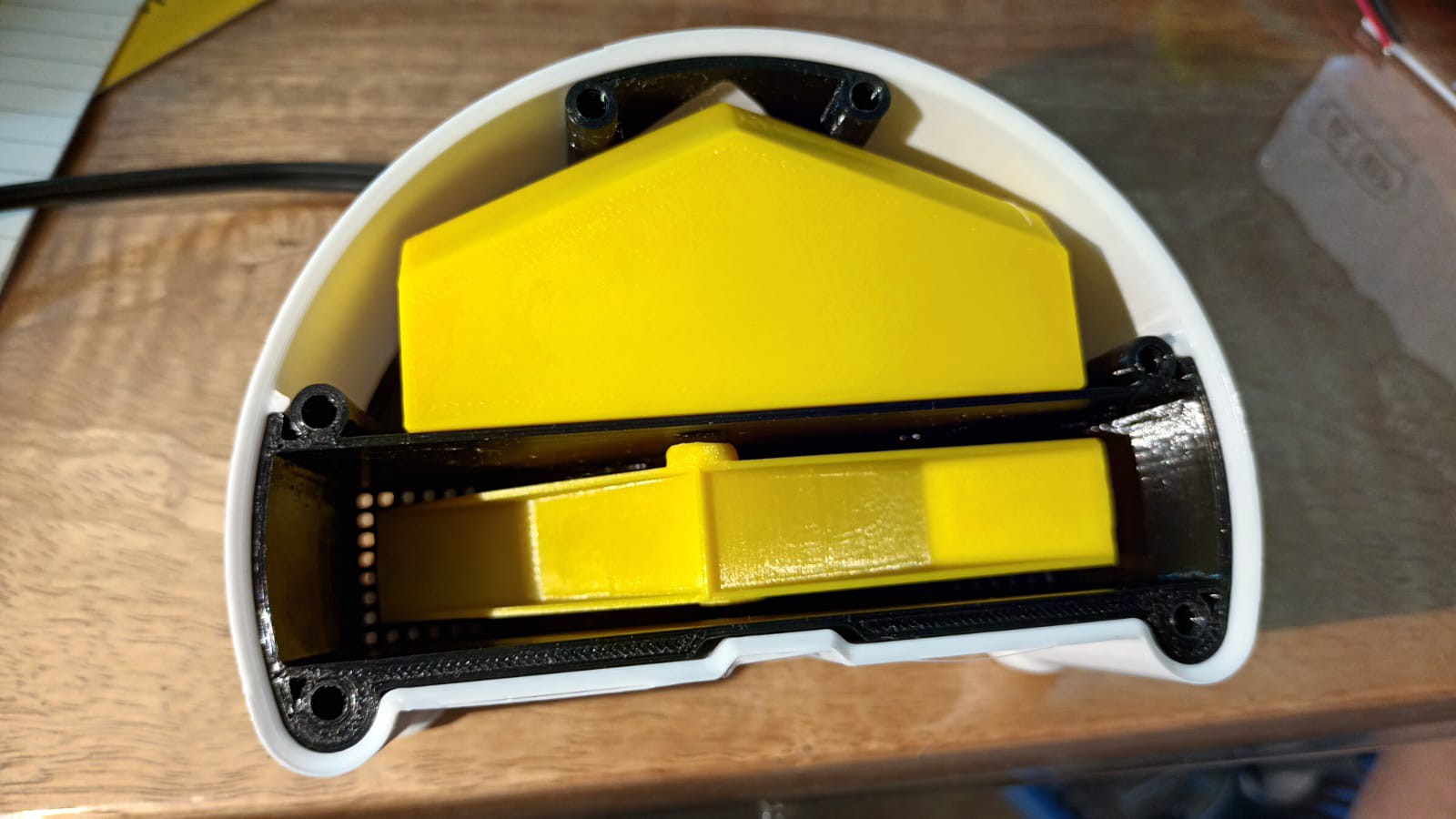

Now the outer shield is slid down over everything, followed by the top, which should press-fit onto the beveled top edge of the shield. The seven small holes in the middle may be slightly constricted as it comes off the printer, so clear them out using a small drill bit (I used 1.4 mm), to ensure that water can pass through reasonably easily. Six M4 x 8 (or longer) stainless steel bolts serve to turn it all into a rugged whole.
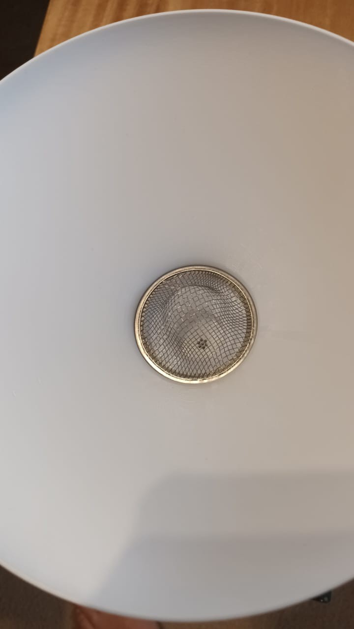
The funnel screws into the top part, but first we need to protect it. So we remove the strainer, and, starting at the small end of the funnel, just above the thread, work up towards the large top edge, both inside and out, carefully burnishing the adhesive aluminium foil onto the printed plastic, in a pretty patchwork of overlapping pieces. Then replace the strainer and screw the funnel into the top part.

The stainless steel sieve measured 53.6 mm in diameter, hence a suitable internal groove was created in the funnel for the sieve to clip into, with some tolerance allowance and to make provision for the thickness of the protective foil cover. The job of the sieve is of course to keep out all kinds of debris which could foul the tipping bucket mechanism, or clog the entry and exit holes, which were kept very small on purpose, to discourage the ubiquitous arachnids and insects. Even if some leaves or avian excrement were to end up in the funnel, the surface area of the sieve is sufficient to ensure that water will still seep through to be counted.
Software Setup
As alluded to above, the ESP board we use runs Tasmota code, which was set up to implement a simple counter on the I/O pin that the Hall effect sensor is connected to, publishing this on the wifi via MQTT. Setting up the board is beyond the scope of this treatise, as is the entire Home Assistant ecosystem, so from this point onwards the assumption is that readers are au fait and actually interested. If not, the hardware can of course be monitored to taste, which, if said taste does not run to HA and Tasmota (or ESPHome), means the following two sections can (and actually should) be ignored, and you can skip to Calibration below.
- Tasmota
One can log directly into the ESP board once Tasmota is running, so this is what I did to set up and even calibrate the sensor.
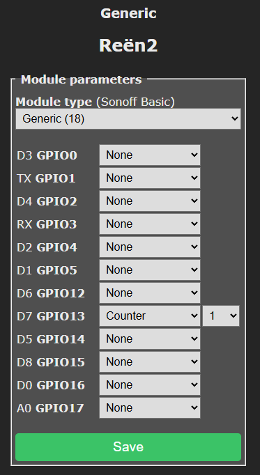
The counter is not of type Counter_n, but of type Counter, which means that the internal pull-up is used. This is needed for our Hall effect sensor (A3144), although an external pull-up resistor would serve equally well.
On the Console screen, the counter is configured with the following commands:
SetOption159 0
countertype 0
counterdebounce 10
counterdebouncelow 10
The first command (SetOption159 0) sets the counter to trigger on falling edges, and the second command (countertype 0) ensures that it is actually a counter, and not a timer. Debouncing is always a good idea, more so when physical contacts, such as in a reed switch, are used (on the Misol with its reed switch we use 50ms debounce time, just to be sure).
- Home Assistant
With Tasmota set up and humming, Home Assistant should see it and have access to the MQTT-published counter value. The Tasmota counter is an unsigned 32-bit value, which could therefore run up to 4 294 967 295, which should be ample for many lifetimes, at a nominal 0.1 mm rainfall resolution. Even in Mawsynram (or maybe López de Micay), supposedly the wettest place on earth, where you could expect some 120 000 counts per year, the counter will take more than 35 000 years to roll over. This means one could let it run indefinitely, and simply set up the rainfall display as a Utility Meter in Home Assistant, which is probably the better idea.
But of course we did not do this, opting instead to reset the counter each day at midnight, by publishing an MQTT message with the payload 0.
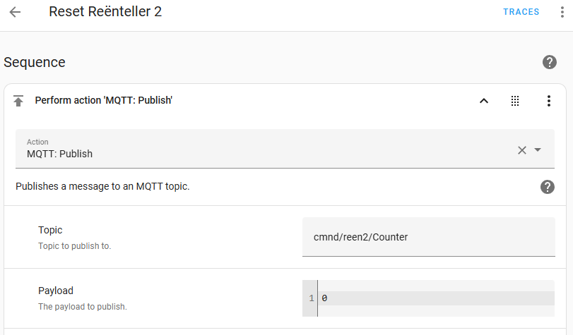
To turn the counts into an actual rainfall reading, we need to compute the value using a template sensor in our configuration.yaml file:
template:
- sensor:
- name: "Reënval (mm)"
unit_of_measurement: "mm"
state: >
{{ '%0.1f'|format(states('sensor.reen2_counter_c1')|float * 0.096) }}
Templating in HA is based on an utterly ridiculous thing called Jinja2, which has to be a joke which somehow got out of hand, as jokes do. (As intimated by the name, it appears as if weed was involved, for no sober person would be able to come up with such a silly and elaborate construct.) It is infinitely sensitive to spaces, underscores, quotes, indents, brackets, character case, odd symbols, and the phase of the moon, which is why, once one gets it working, after wrangling weird and wonderful combinations of spaces, tabs, underscores, and especially brackets of all types, one tries not to touch it ever again, except to reuse in something hopefully similar. This is why I kindly show above what worked for me – the only thing I ever change, with trepidation, is the final calibration value at the end (the value of 0.096 before the three closing brackets). We are aiming at about 0.1 mm resolution, hence the formatting to display only one digit after the decimal. Save the configuration.yaml file, then go to Developer Tools, and under YAML configuration reloading click on Template Entities. This should result in the template sensor becoming available for use and display. In this example case it is called Reënval (mm) –you are likely to prefer something different, so edit the name entry accordingly.
- Calibration
And at last we get to calibration. We need to determine how much water is needed to make the mechanism tip. To do this I placed the entire device on top of a drinking glass, inside a large mixing bowl. This way it can be upright and level, and water can exit freely through the gratings at the bottom, the holes of which are many but intentionally tiny, once again to dissuade arthropods from colonising the inside. The mixing bowl and glass will catch all water passing through the machine, allowing us to measure its weight/volume.
After emptying the bowl and resetting the counter, we start dripping water into the funnel, while keeping an eye on the counter. I devised a setup with a drip-type pinched pipe, which enabled me to restrict the flow to about two drops per second, to approximate a reasonable rain rate. We keep going until the count reaches 100 (as with chocolate, more is always better, but life is also short). Then we instantly stop the water feed and gently shake the device to allow the last of the water still inside it to also drop into the mixing bowl. This shaking is likely to trigger the counter lots more times, but that is OK – we ignore it, because we can remember that we stopped at 100 counts, or wherever it was, and that is the value we shall use.
Weighing the water in the bowl and dividing by the final count gives us the average amount per tip of the mechanism. Because the mechanism is bound to be slightly asymmetrical, it is a good idea to use an even number of counts – the larger the better.
Example calibration results:
| Counts | 100 | |
| Water weight | 118 | g |
| Avg. volume per count | 1.18 | cm3 |
| Funnel diameter | 12.5 | cm |
| Catchment Area | 122.7185 | cm2 |
| mm of rain per count | 0.096155 | mm/count |
In this case we measured 118 ml of water in the bowl after 100 counts, which means we tipped after an average of 1.18 ml of water. Now we just divide this by the catchment area (computed from the funnel diameter), and fix the units. Hitherto we were working in centimetres (and powers thereof), but we desire to measure rain in millimetres. If the funnel diameter as printed came out at 125 mm (12.5 cm), this means that each tip is equivalent to 0.096 mm of rain, hence our calibration value used in the example template above. Had we used the bigger (150 mm) funnel, the calibration factor would have been about 0.067 mm/count.