 Jamie Ashton
The Circuit
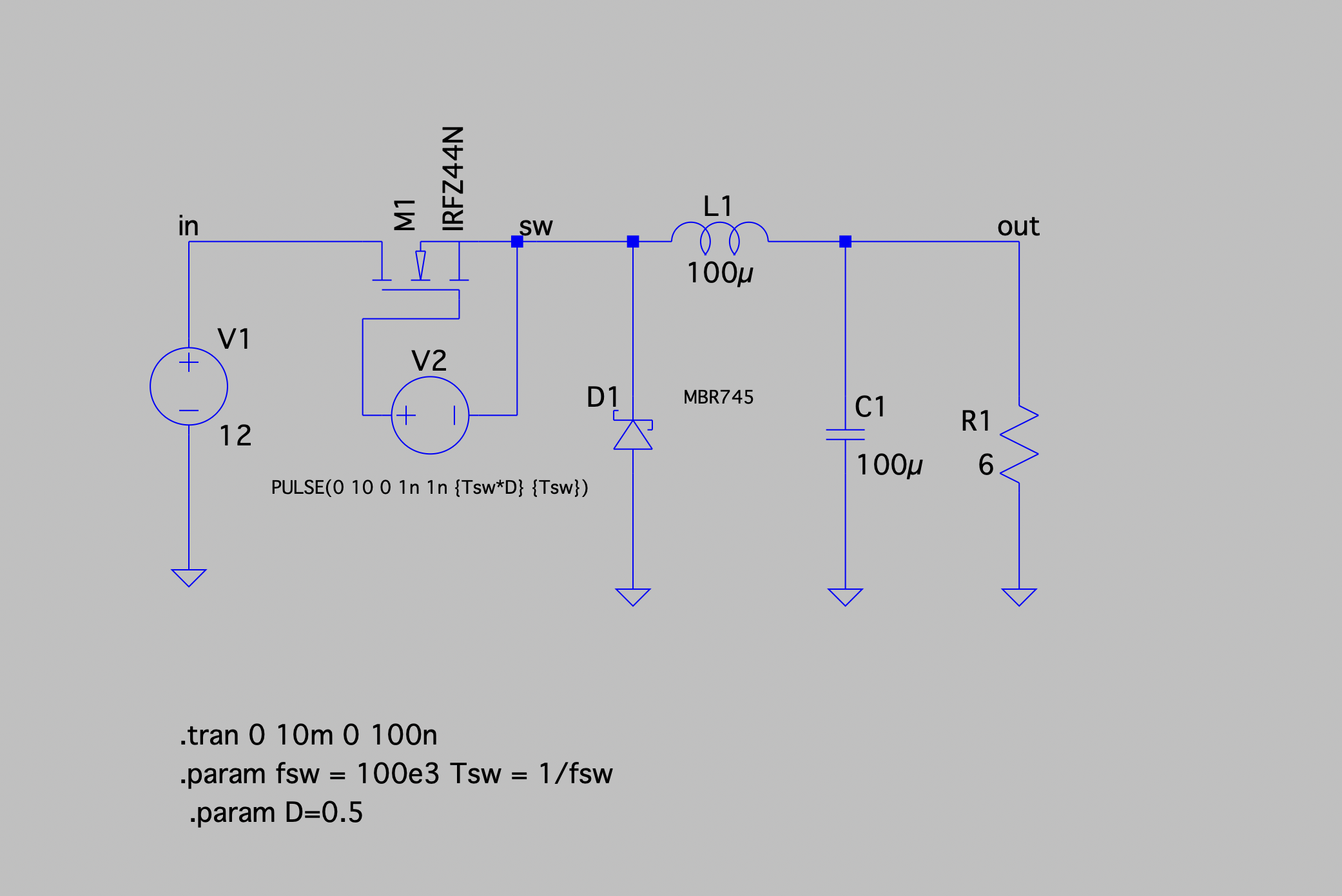
I started by creating a simple buck converter in LTSpice. This circuit steps-down a 12V input by adjusting the PWM signal supplied to the IRLZ44N MOSFET power transistor which acts as the switching transistor. I chose a 100 uF capacitor and 100 uH inductor to start with, and will investigate the effects of changing these component values in time. The free-wheel diode chosen was the MBR745 Schottky diode, as its ratings are well within safe ranges for this circuit. Additionally it has fast recovery and a low forward voltage drop.
The Simulation

The Schematic
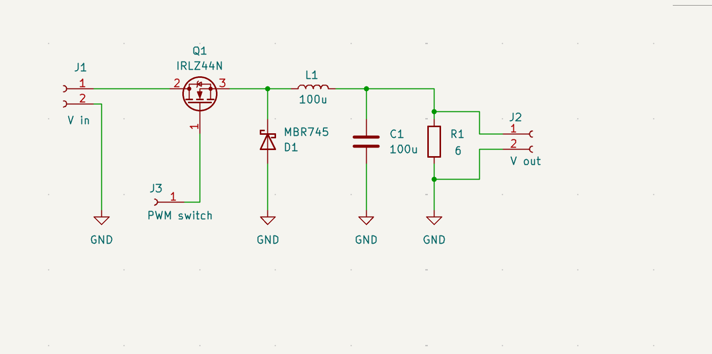
The switching of the transistor is controlled by a PWM output signal from a microcontroller, wired at J3.
The PCB
Discussions
Become a Hackaday.io Member
Create an account to leave a comment. Already have an account? Log In.