 jenna
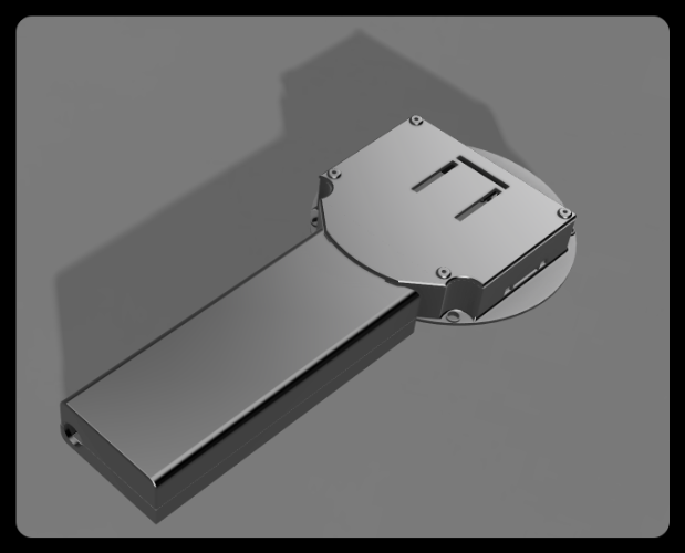
jennaThe SensorCam P4 is a handheld device similar in shape to a magnifying glass. To ensure convenience during 3D printing, we divided the device into the handle and the head. The overall design is shown in the figure below:
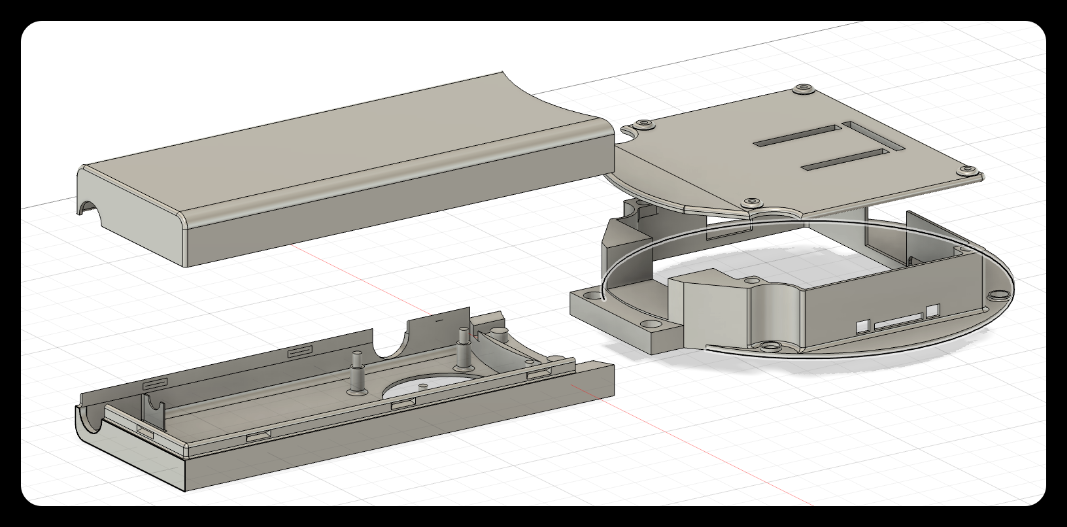
- The handle and the head are connected through a mortise and tenon joint,
- the front cover and the back cover of the handle are combined by means of a buckle,
- and the back cover of the head and the main body are combined by magnetic attraction.
The combined state is shown in the figure below:
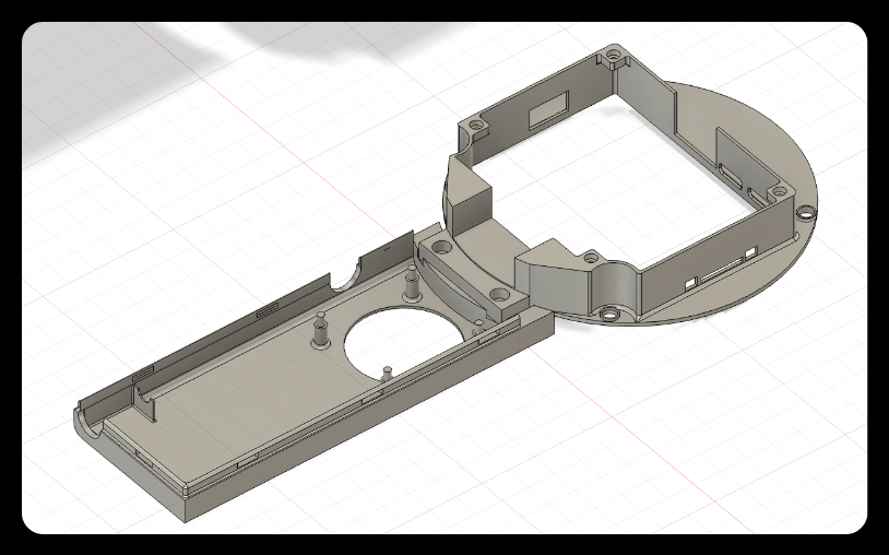
1. Diagram of the connection between the handle and the head
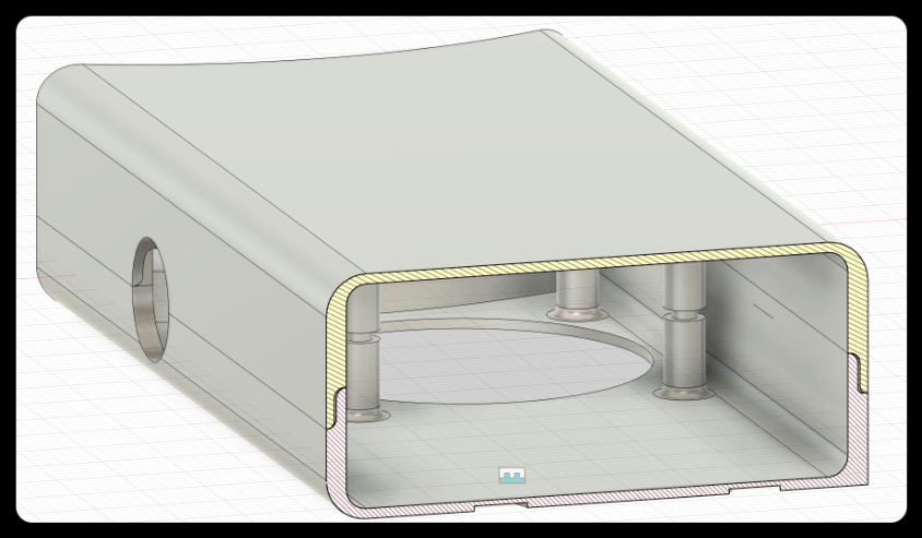
2. Connection Diagram of Handle Front and Rear Covers (Cross Section)
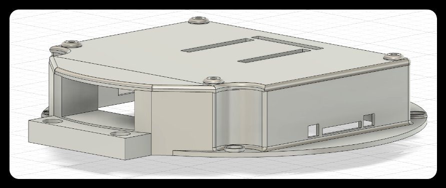
3. Magnetic connection diagram of the head and the back cover
Below are the design details of each module.
Head
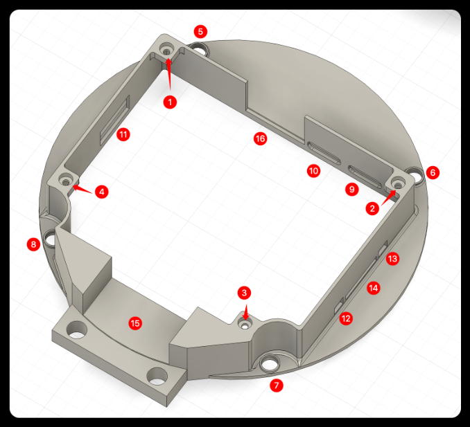
❶❷❸❹: Magnet placement slot.
❺❻❼❽: Screw fixing hole.
❾❿: Type-c port.
⓫: USB port.
⓬⓭: Button port.
⓮: SD card port.
⓯: Wire channel.
⓰: Reserved space for camera interface.
Head cover
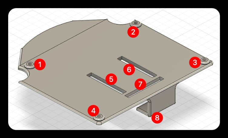
❶❷❸❹: Magnet placement slot.
❺❻❼: Reserved slot for the female header of the main adapter board.
❽: Adapter board support, preventing the adapter board from deforming inward when the module is inserted.
Handle back cover
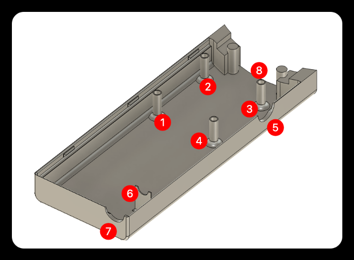
❶❷❸❹: Coupling female socket.
❺: Knob reserved hole.
❻❼: Battery DC charging port support.
❽: Wire channel.
Overall effect
Front Side
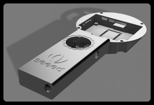
Back Side
Discussions
Become a Hackaday.io Member
Create an account to leave a comment. Already have an account? Log In.