 Mitsuru Yamada
1. Equatorial mount
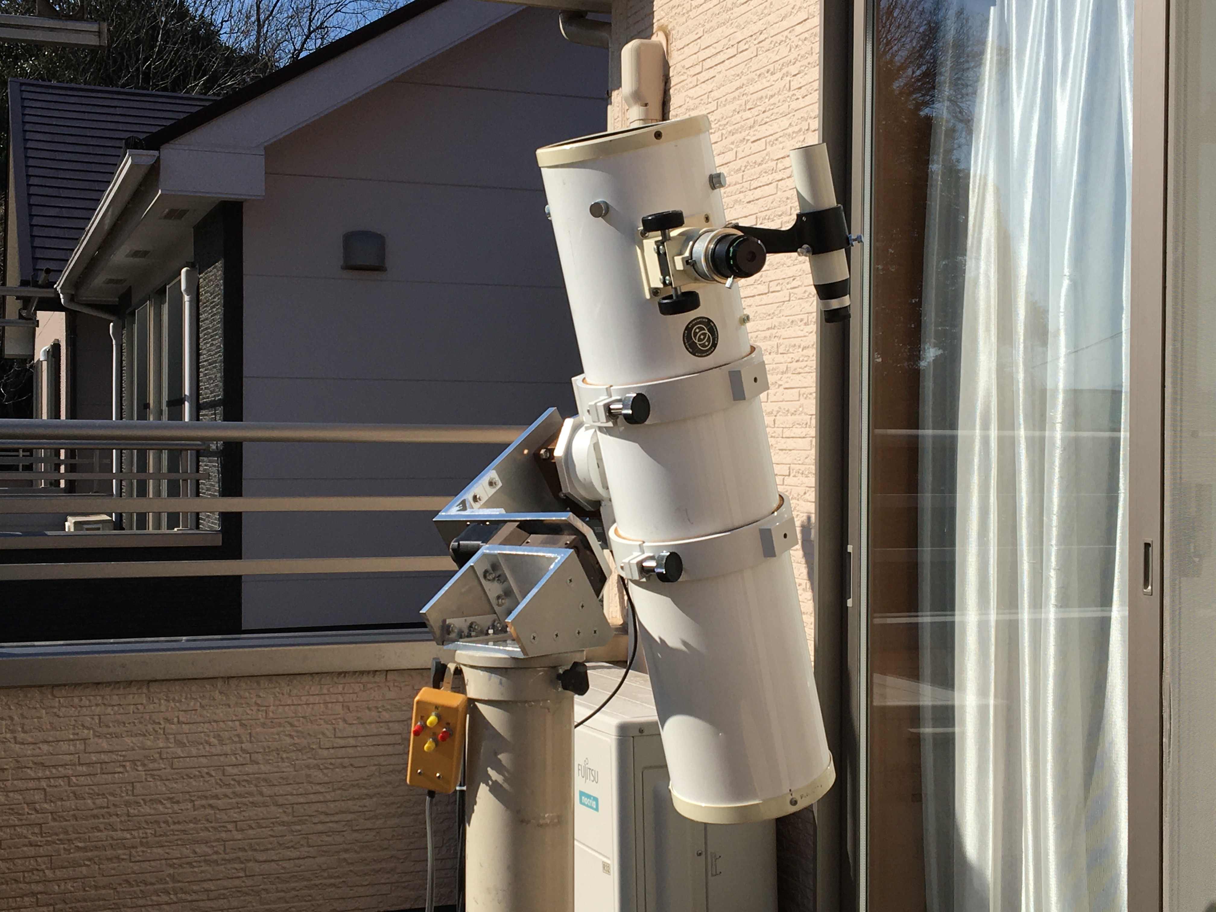
The equatorial mount for an astronomical telescope that I had built in a previous project was operational for astronomical observation with a small telescope. However, since the payload was about 5 kg, it was impossible to mount a telescope with an aperture of 20 cm class, which is effective for planetary observation, and furthermore, it was completely impossible to mount a telescope with an aperture of 30 cm class. To solve this problem, I decided to build the YTM-4 with a mechanical part that is 1.5 times larger than the previous YTM-3. Figure 1 shows the YTM-4 with a 30cm Newtonian telescope mounted.

Fig. 1 YTM-4 single arm equatorial mount with a Orion Optics UK's 30cm F4 Newtonian optical tube.
The equatorial mount is a single arm type, which was adopted this time as well, since it was understood in the final state of YTM-3 that the single arm type, in which the optical tube is mounted on the inside of the arm, can increase the payload capacity with a smaller load on the motor. The advantages of this type are that it does not require a counterweight, which is almost the same weight as the optical tube in the German type, and that the optical tube does not need to be moved from the west side to the east side of the equatorial mount when the observed object passes south-central. On the other hand, the disadvantage is that the length of the arm needs to be considerably increased in order to increase the operating range in the Dec. axis.
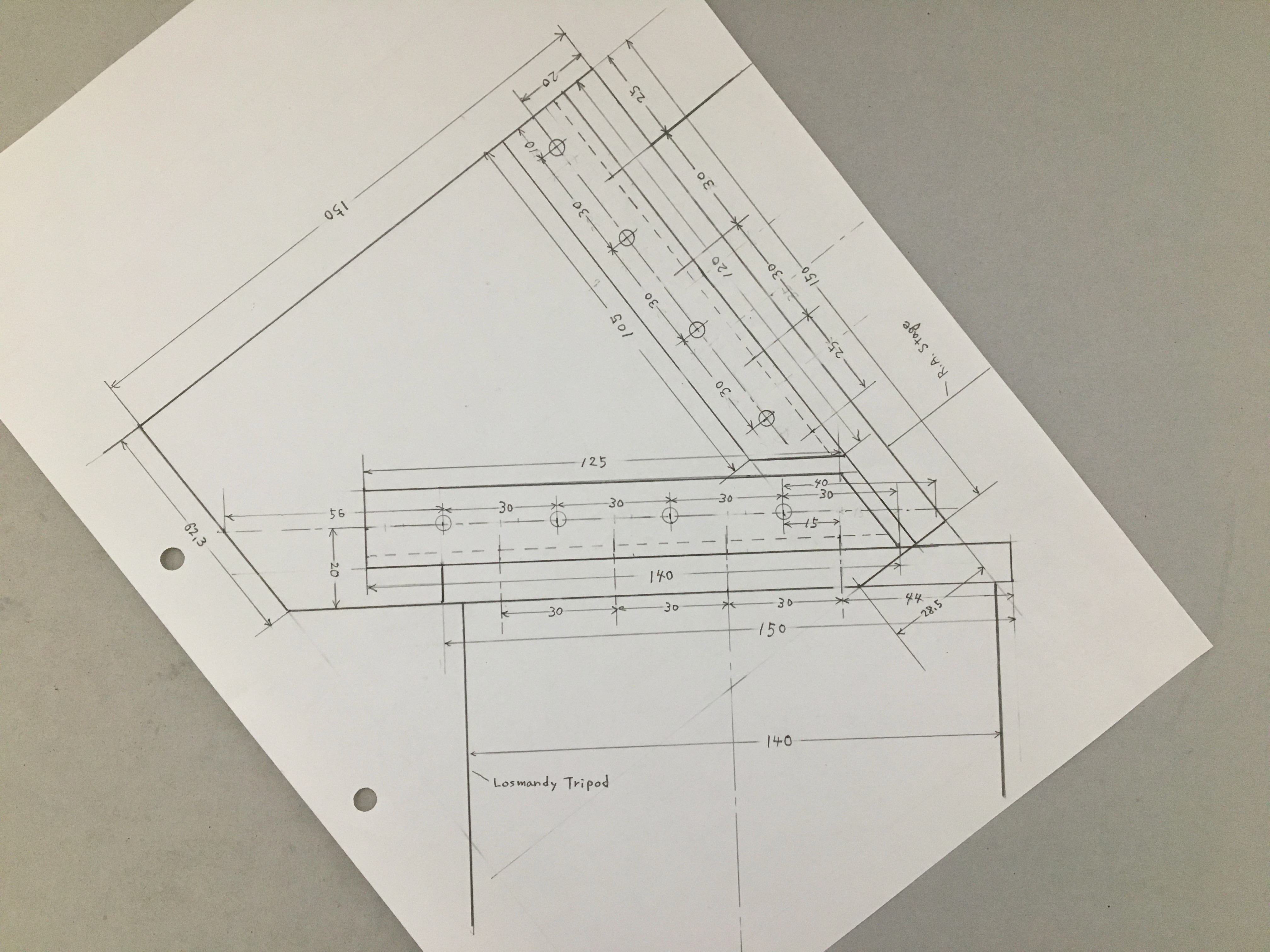
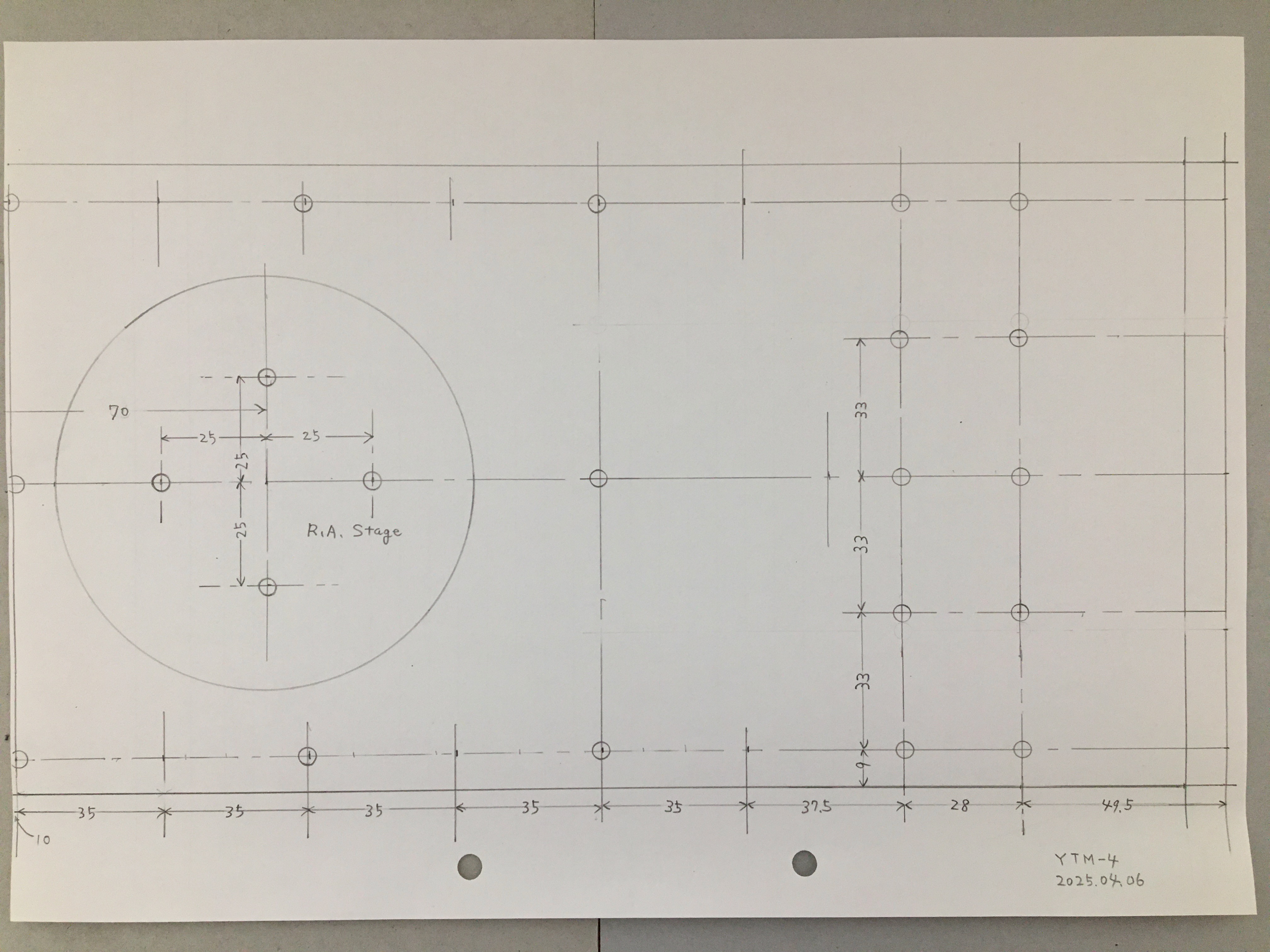
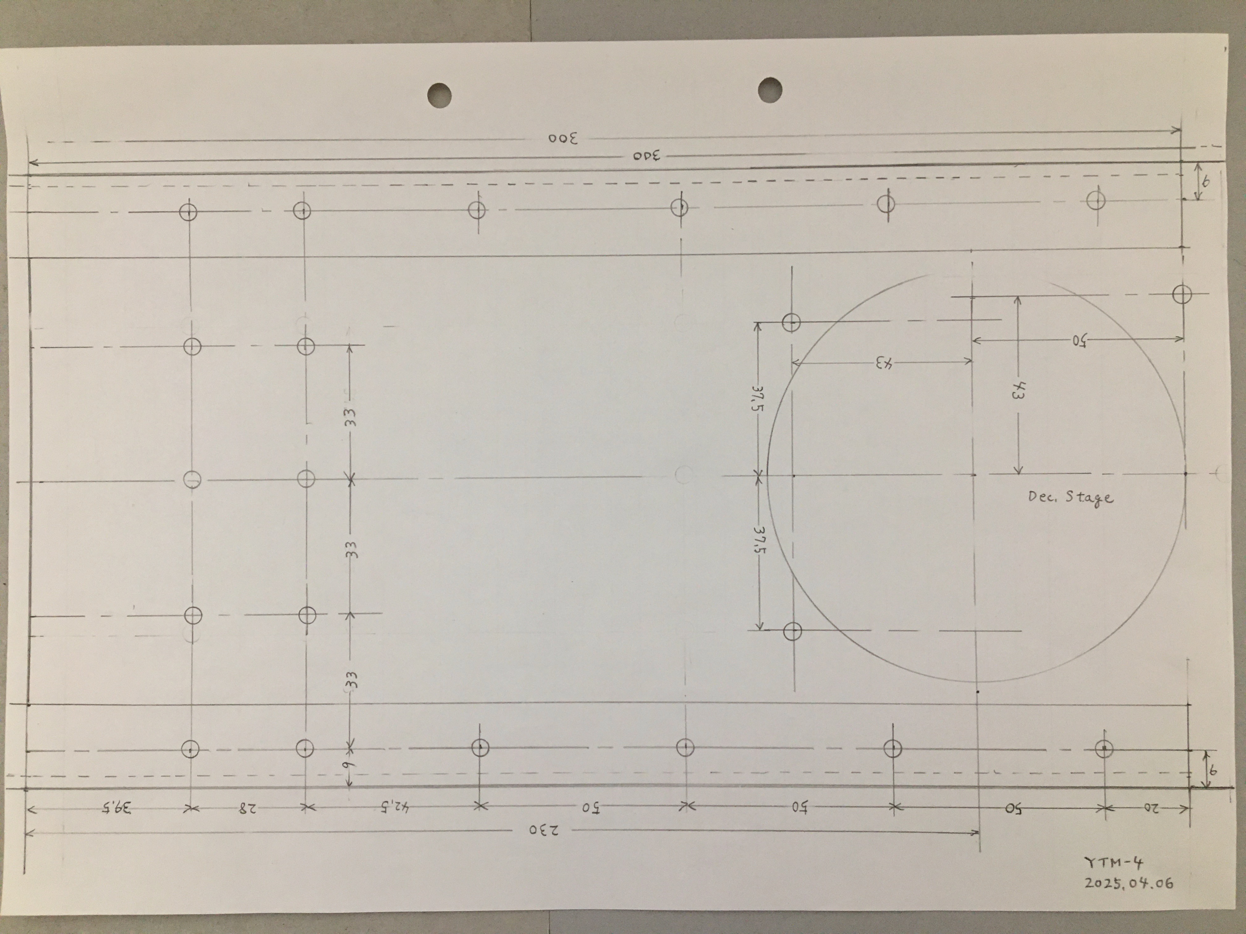
In YTM-3, the structure was built by machining a 10mm thick, 100mm wide aluminum plate, but this has been increased to 150 mm wide. The length of the arm structure has been changed from 200 mm per side to 300 mm. The thickness of the plate is the same as before, 10 mm, for ease of fabrication, but the arm is made of two layers and add L-angles to increase its strength. I used a small band saw and a drilling machine to process the aluminum plates.
Figure 2 shows the appearance of YTM-4. The polar axis body is fixed on to the tripod. The R.A. axis rotary stage is bolted to the polar axis body surface of perpendicular to the polar axis. The arm structure is bolted to the top of the R.A. axis rotary stage. And the arm structure is made up of the plate 1/2 and the plate 2/2 joined at a right angle. The Dec. axis rotary stage is bolted to the plate 2/2, and a connection plate for fixing the optical tube is bolted to the top of the Dec. rotary stage.
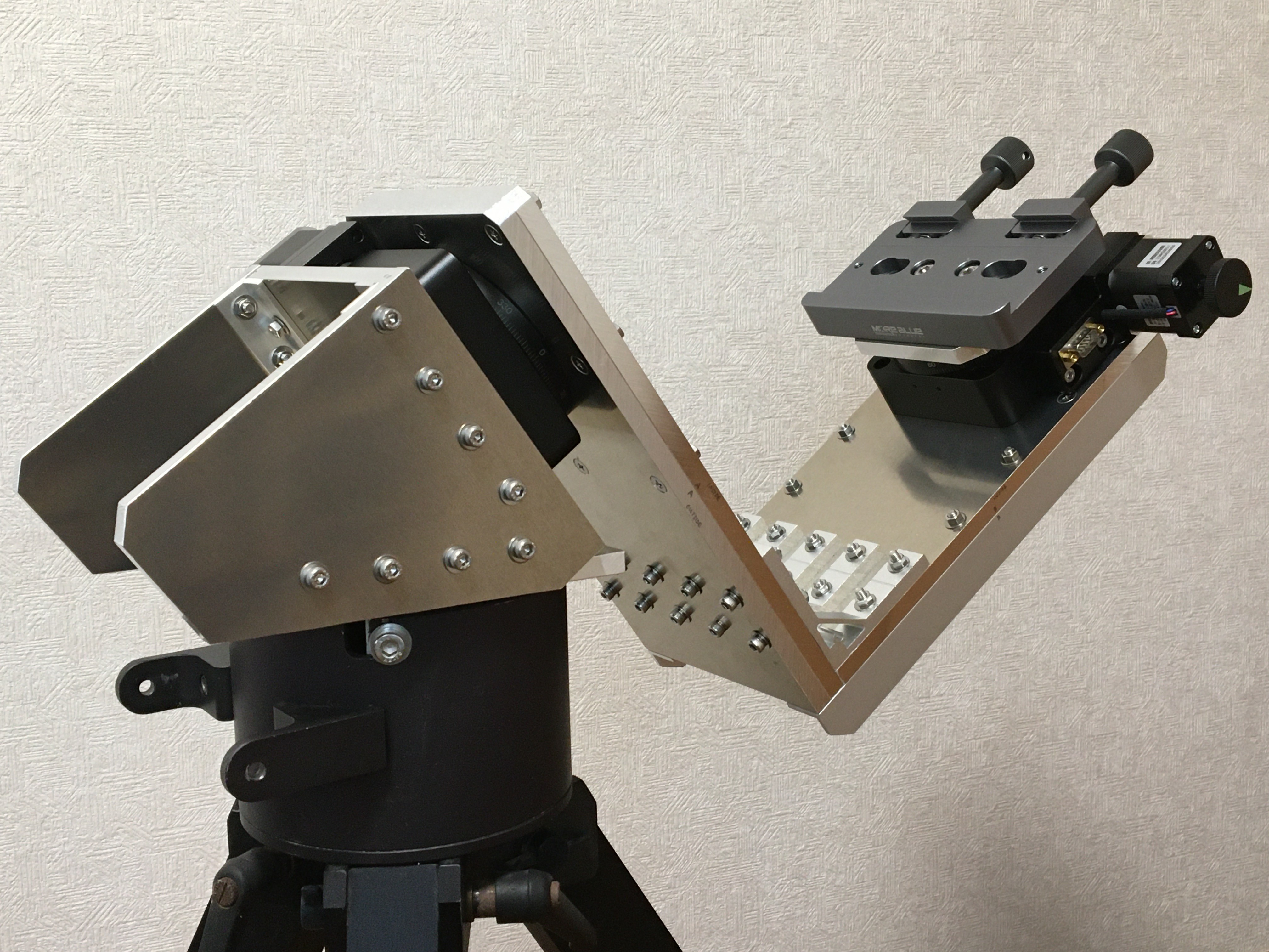
Fig. 2 YTM-4 Single arm equatorial mount.
2. Gear section
The gear section of R.A. and Dec. axis of YTM-3 used a motorized rotary stage Y200RA60 with a diameter of 60 mm, but since the strength of this section needed to be increased, an HT03RA100 with a diameter of 100 mm was used for this section as shown in Fig. 3. The stepper motor is the same 42-type as the 60-mm-diameter one, and the connector pin connection for the coil terminals is also the same. Although a larger gear diameter would have been preferable, the next largest type of rotary stage available is 200 mm in diameter, and its weight, price, and the entire equatorial mount would have been too large for this concept, so I did not use this type. The reduction ratio of the worm gear was increased from 90:1 to 180:1, so the control pulse had to be adjusted to the new ratio.
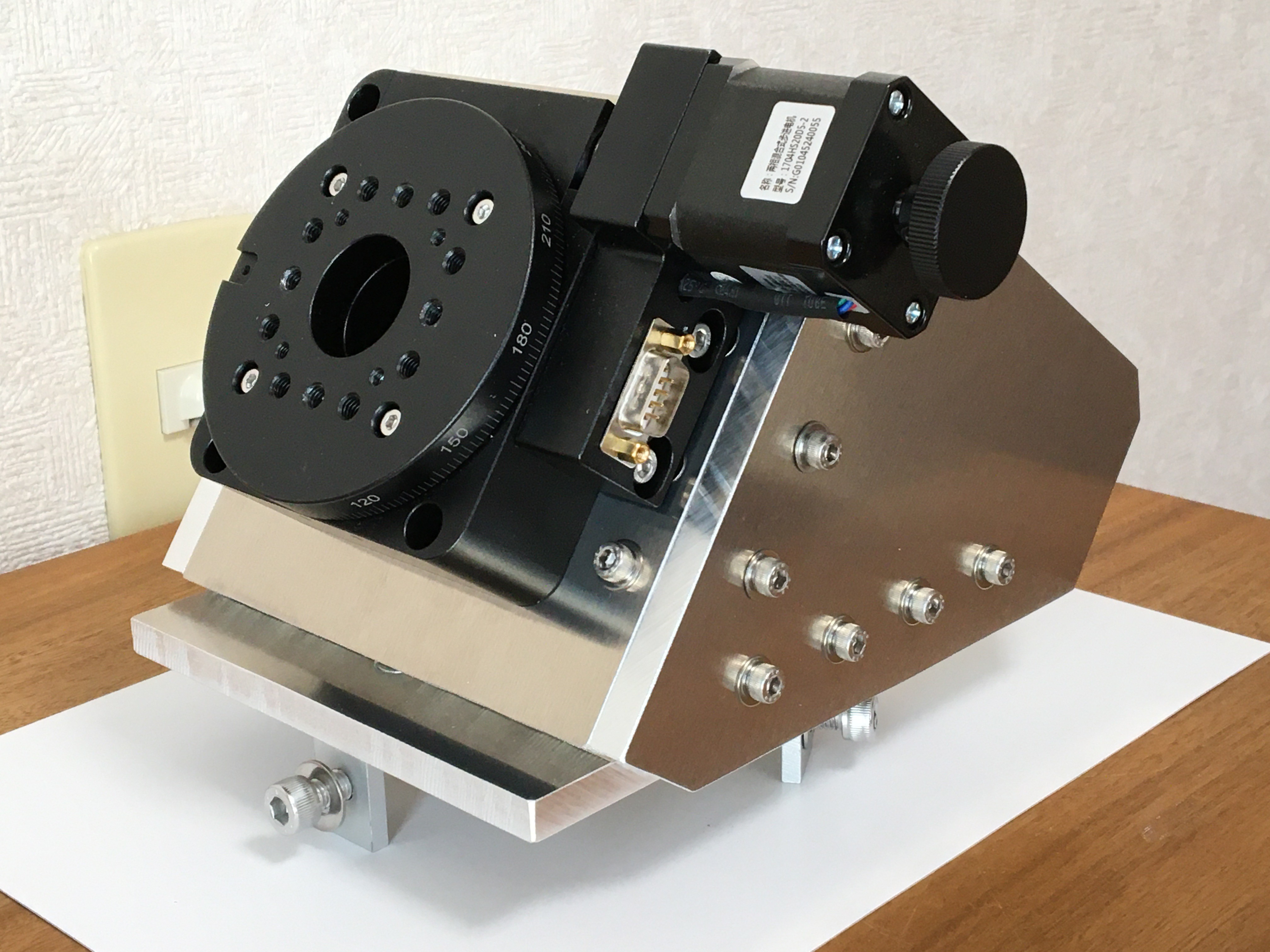
Fig. 3 100mm diameter motorized rotary stage and the polar axis body.
4. Controller section
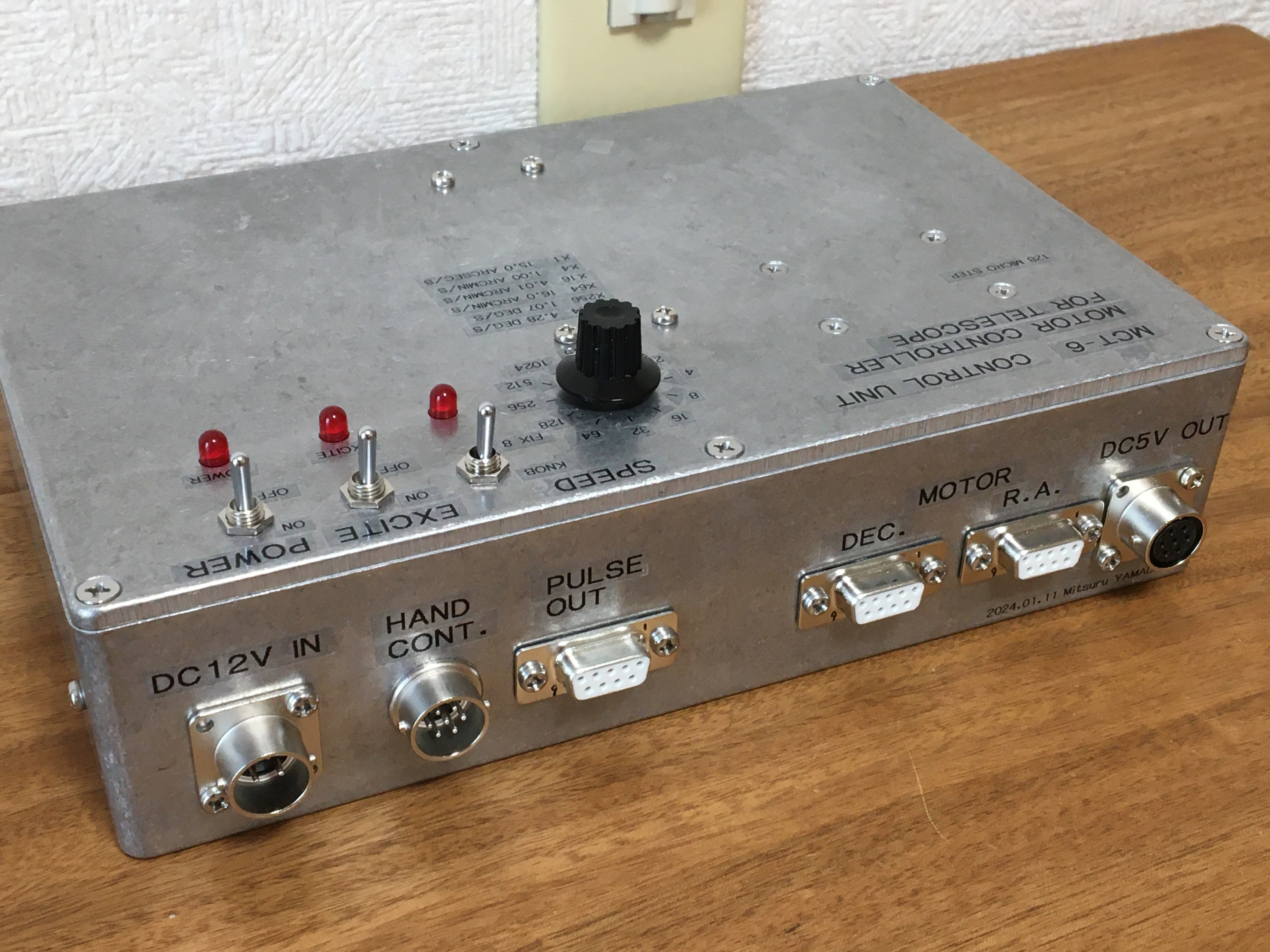
The control unit and counting unit are from the MCT-6 project. To cope with the difference in worm gear reduction ratios, I first considered changing the clock frequency divider circuit. However, it turned out that this would require changing the frequency divider circuit of the counting unit as well, resulting in a loss of compatibility with the existing system as a whole. I decided to test the system with the micro-step driver DM542 with the division ratio setting changed from 128 to 64, with no change in the circuit structure shown in Fig.4. The value of this specification change is shown in red in this figure. The setting value of the turning speed with the knob on the control unit was also the same as before, from 0.5x to 1024x. The peak current setting of the motor drive was changed to 1.5A because the motor sometimes stalled when the current setting was 1.0A.
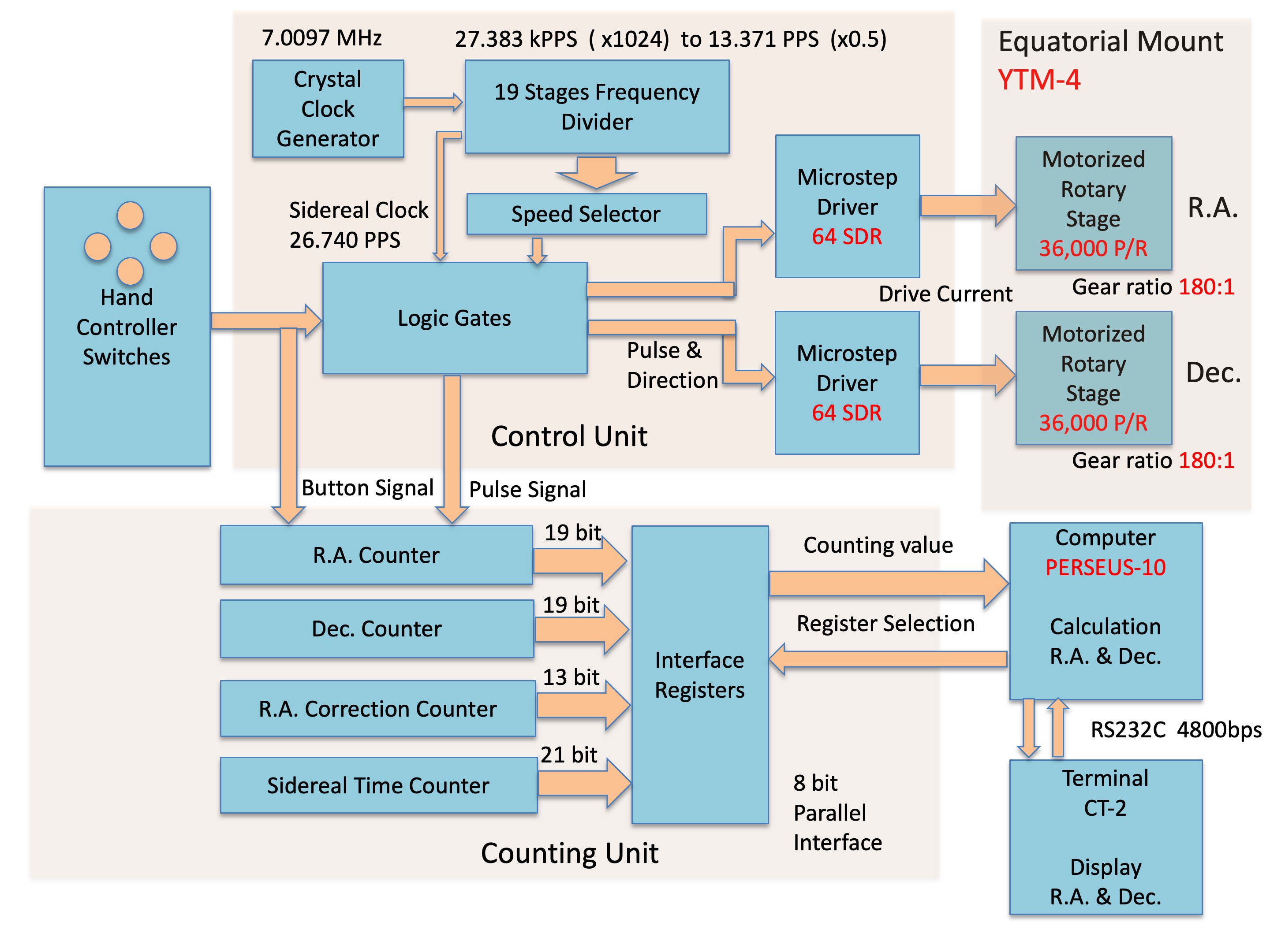
Fig.4 Control section MCT-6 diagram for YTM-4.
5. Computer Section
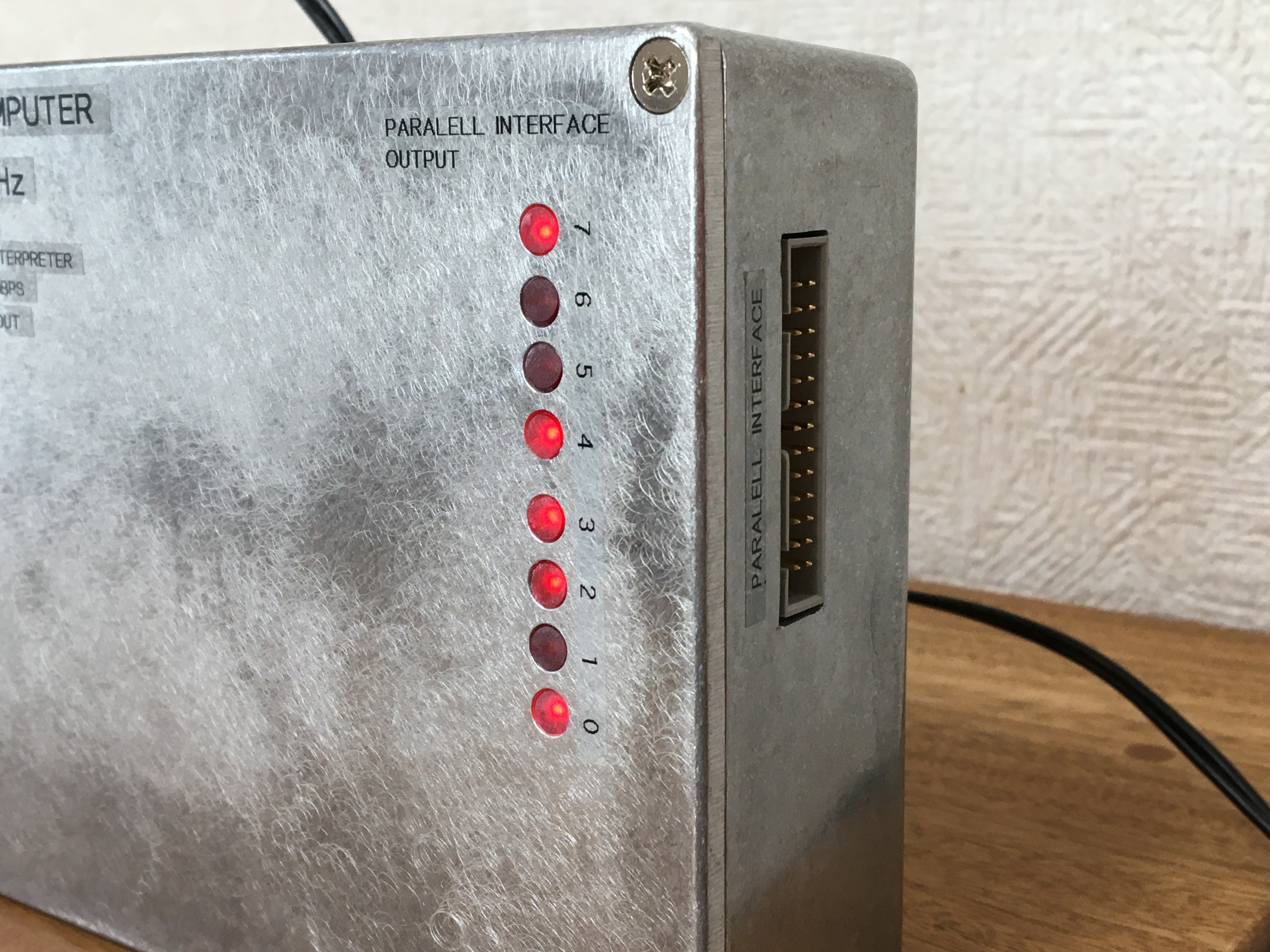
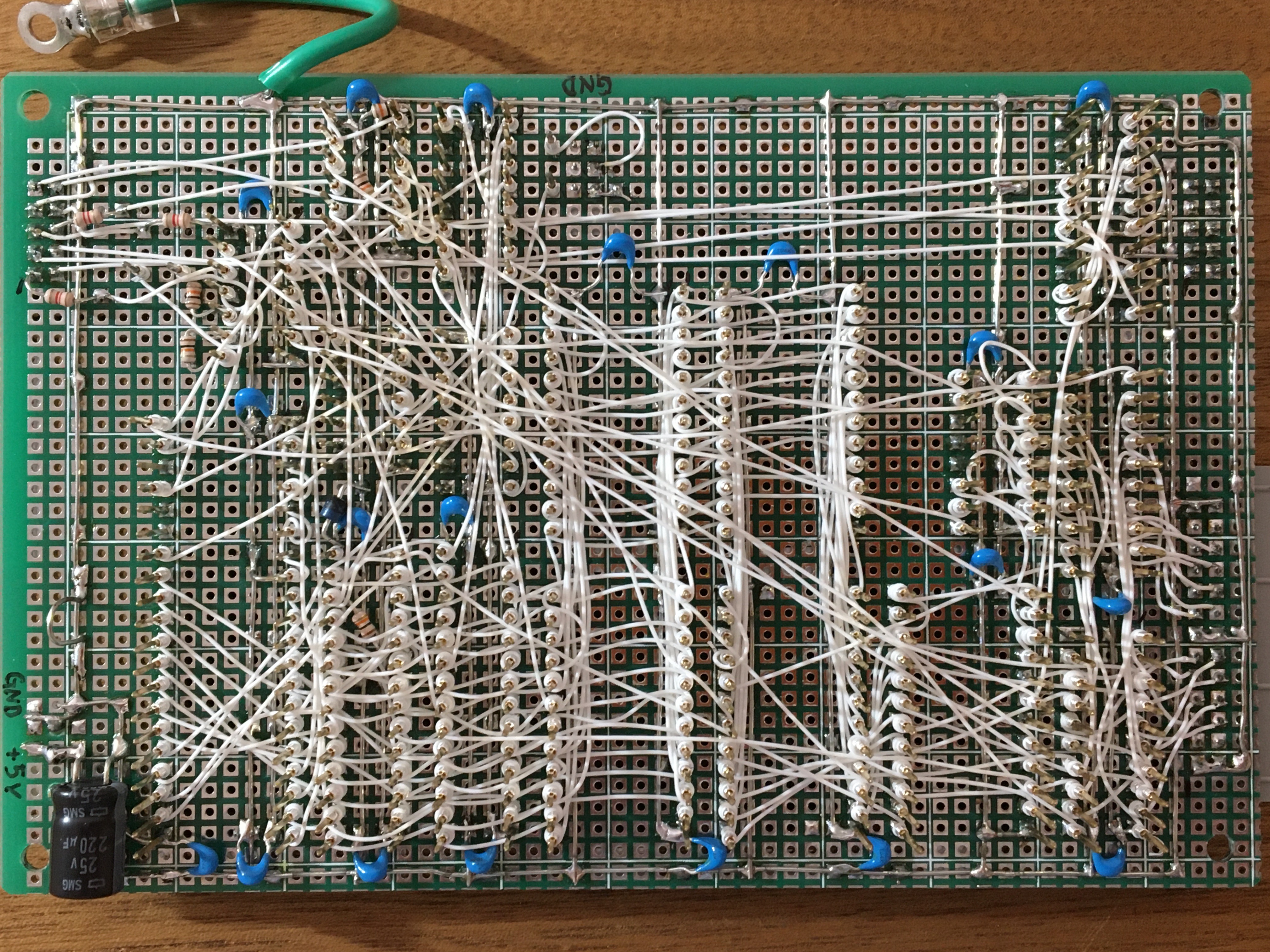
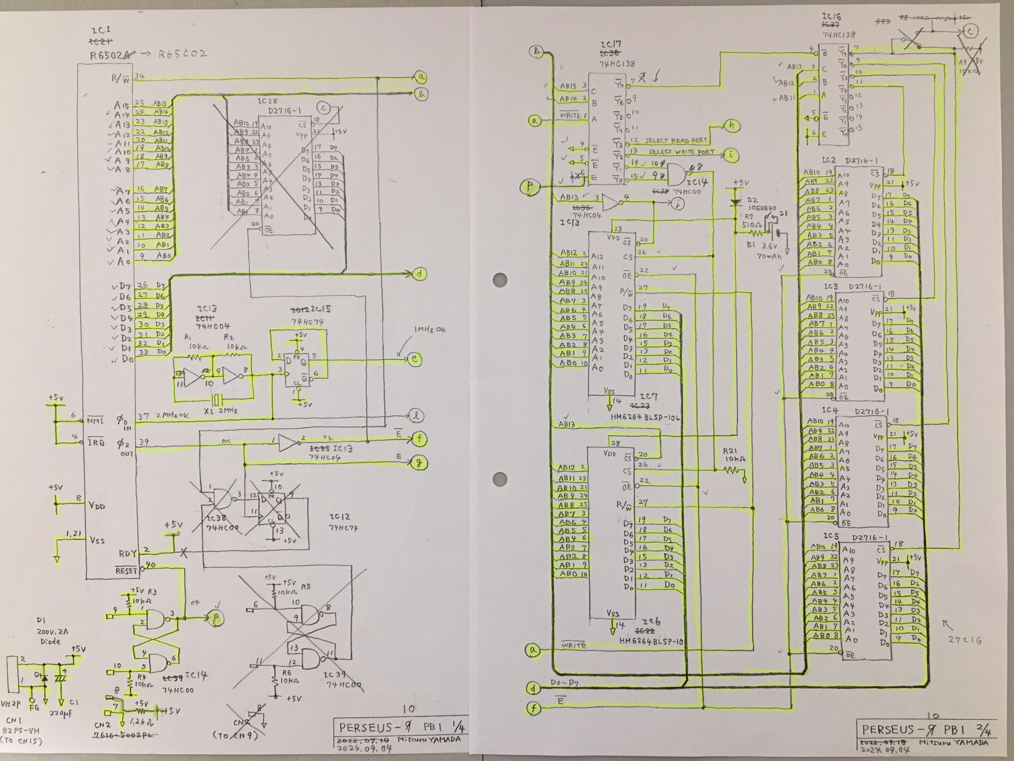
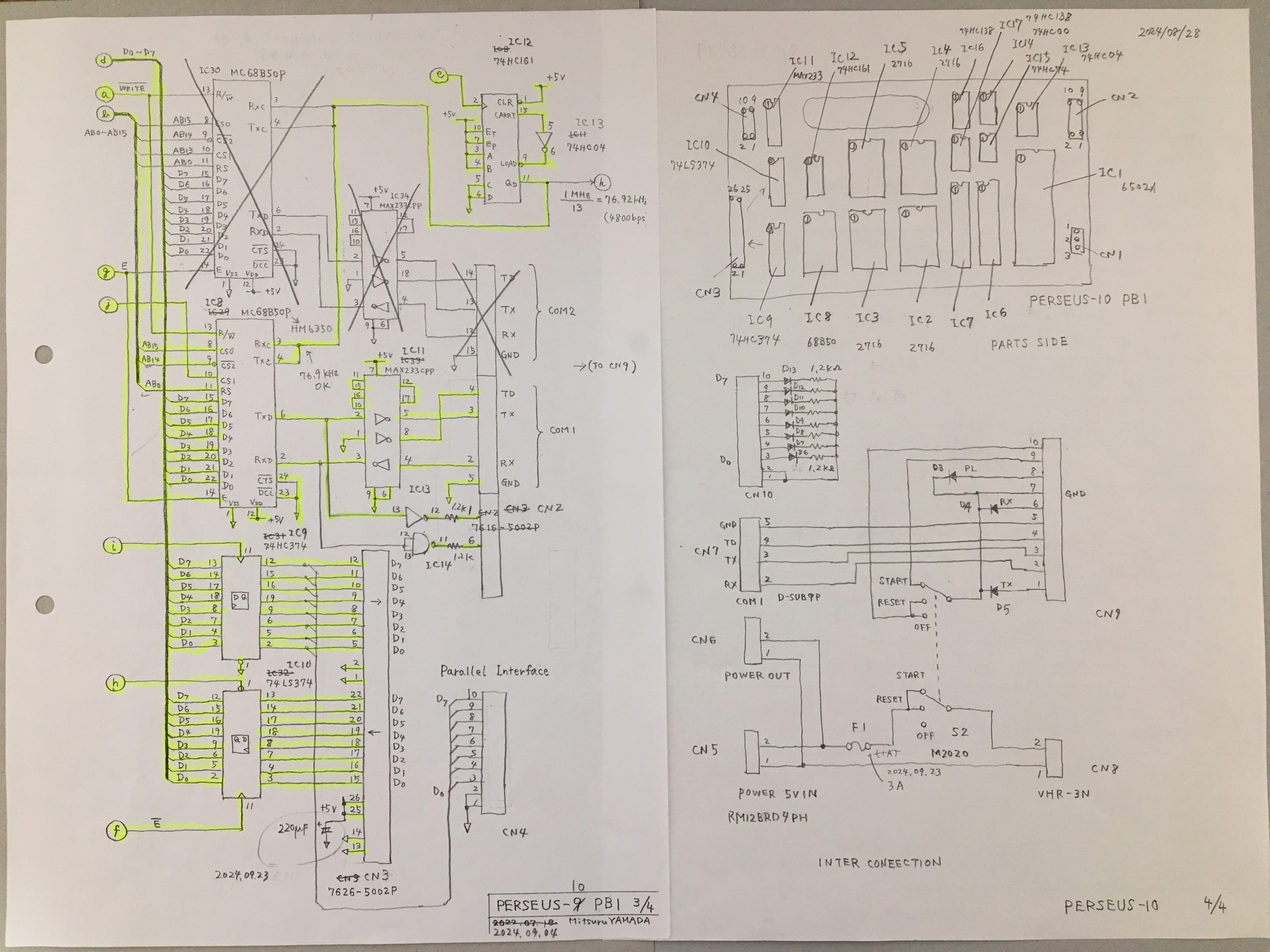
In the previous project, PERSEUS-9 was used to read counting values from the counting unit, convert them to R.A. Dec. values, and display them, but I newly built PERSEUS-10 for dedicated use in telescope operation. The PERSEUS-10, shown in Fig. 5, is a circuit board with the keyboard, display, and 2nd CPU removed from the PERSEUS-9, and is housed in a 18cm x 12cm x 5 cm small die-cast case. The 8-bit parallel interface has a bit information indicator. Figure 6 shows an inside of PERSEUS-10. The wiring side of the board is shown in an attached file. The schematic diagram is shown in attached file 1/4, 2/4 and file 3/4, 4/4.
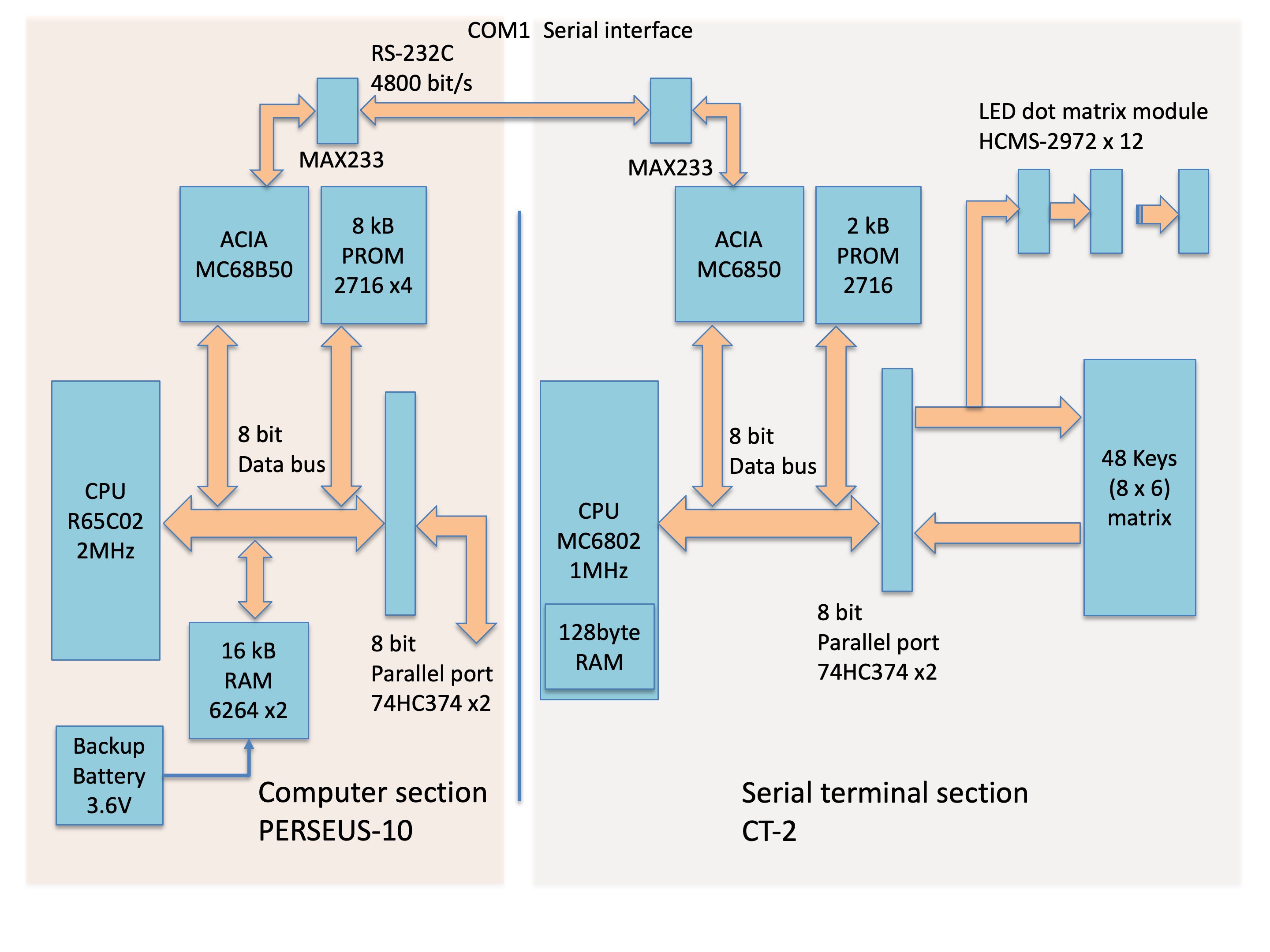
Fig. 5 Computer section diagram of YTM-4.
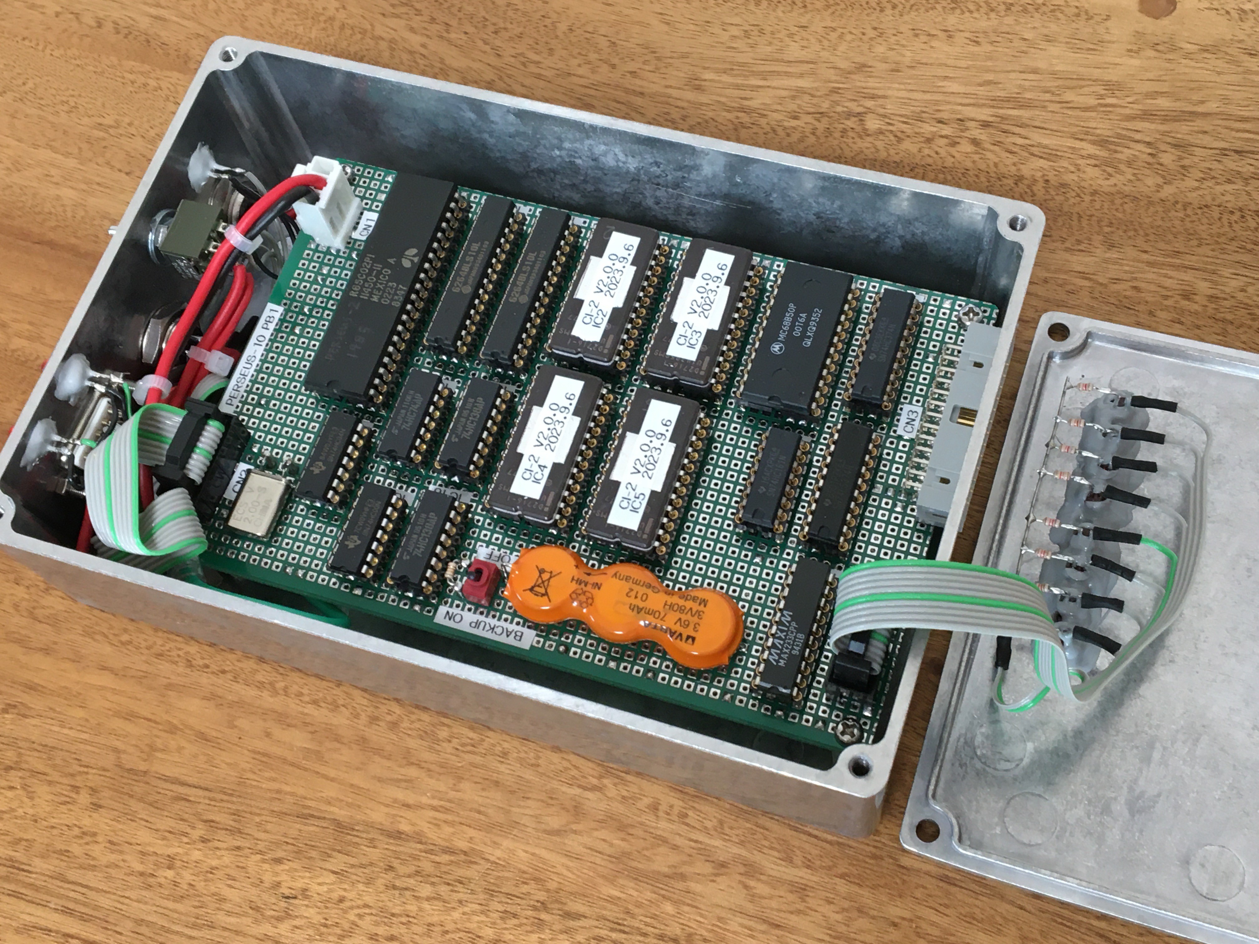
Fig. 6 Inside of the computer section PERSEUS-10.
The system software for PERSEUS-10 is the same CI-2 homemade floating point interpreter as for PERSEUS-9. The application program input via the serial or parallel interface is battery-backed in RAM, so that the operating process can be performed immediately after power-on. For the display of R.A. and Dec. values and keyboard input of alignment values, I decided to use the CT-2 6802 Serial Terminal shown in Fig. 5 and Fig. 7 which was introduced in a previous project.
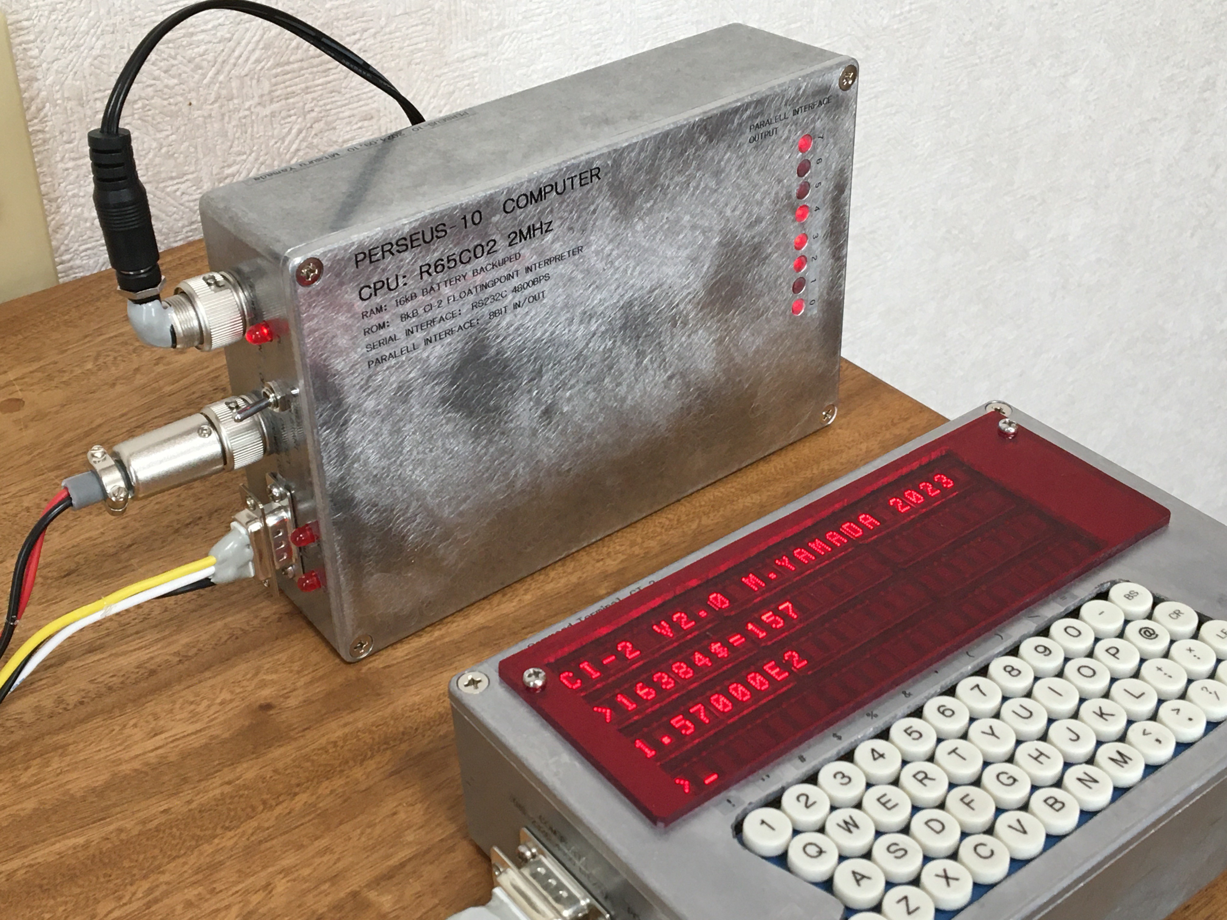
Fig. 7 CT-2 6802 Serial Terminal and PERSEUS-10 65C02 computer.
6. Display software
The program description language specification is the same as that of PERSEUS-9, a home-made floating-point interpreter. However, while PERSEUS-9 has 40 characters per line, this terminal CT-2 has 24 characters, so the R.A. and Dec. display software is MCT-6_1.TXT with the sidereal time display removed. And since CT-2 has a 1MHz MC6802 CPU, the display processing capability is about 2.5 times slower than PERSEUS-9's 2MHz, 6502. Therefore, the entire processing was simplified and the program was devised so that the display rate would not slow down too much.
The MCT-6_1.TXT is shown in attached file. This MCT-6_1.TXT is stored in two 2716PROMs on the external storage EXTROM-2 to allow loading into PERSEUS-10, so that the program length is within 4kB. Further, I have developed MCT-6_4.TXT to speed up the display update speed. In this program, the 1-second digits in R.A. and the display of less than 10 arc seconds in Dec. were removed.
7. Result
The self-weight of YTM-4 is 12kg. The YTM-4 equatorial mount was equipped with a Newtonian optical tube of 30cm F4 aperture weighting 14kg, and was able to make a slewing at 256x speed for tracking. I observed Jupiter at 400x visual magnification to confirm that no micro-vibrations were observed during tracking.
The range of movement in the Dec. axis is +/- 24 degrees for this 34cm diameter optical tube due to interference with the bottom of the declination arm. The range of movement can be increased by lengthening the arm, but this requires more mechanical strength and there is a risk that the center of gravity may exceed the ground position of the northern tripod, causing it to tip over. So, I will observation of the zenith or the northern sky is particularly necessary, a 20cm class Cassegrain-type telescope will be mounted and operated. This type of telescope has a particularly short optical tube bottom, which considerably improves the problem of interference with the bottom of the equatorial arm.
Video 1 below shows the mechanical assembly of YTM-4, the inside of PERSEUS-10, and a slewing test. This video has no audio commentary, so please turn on subtitles.
Video 1 Introduction of YTM-4.
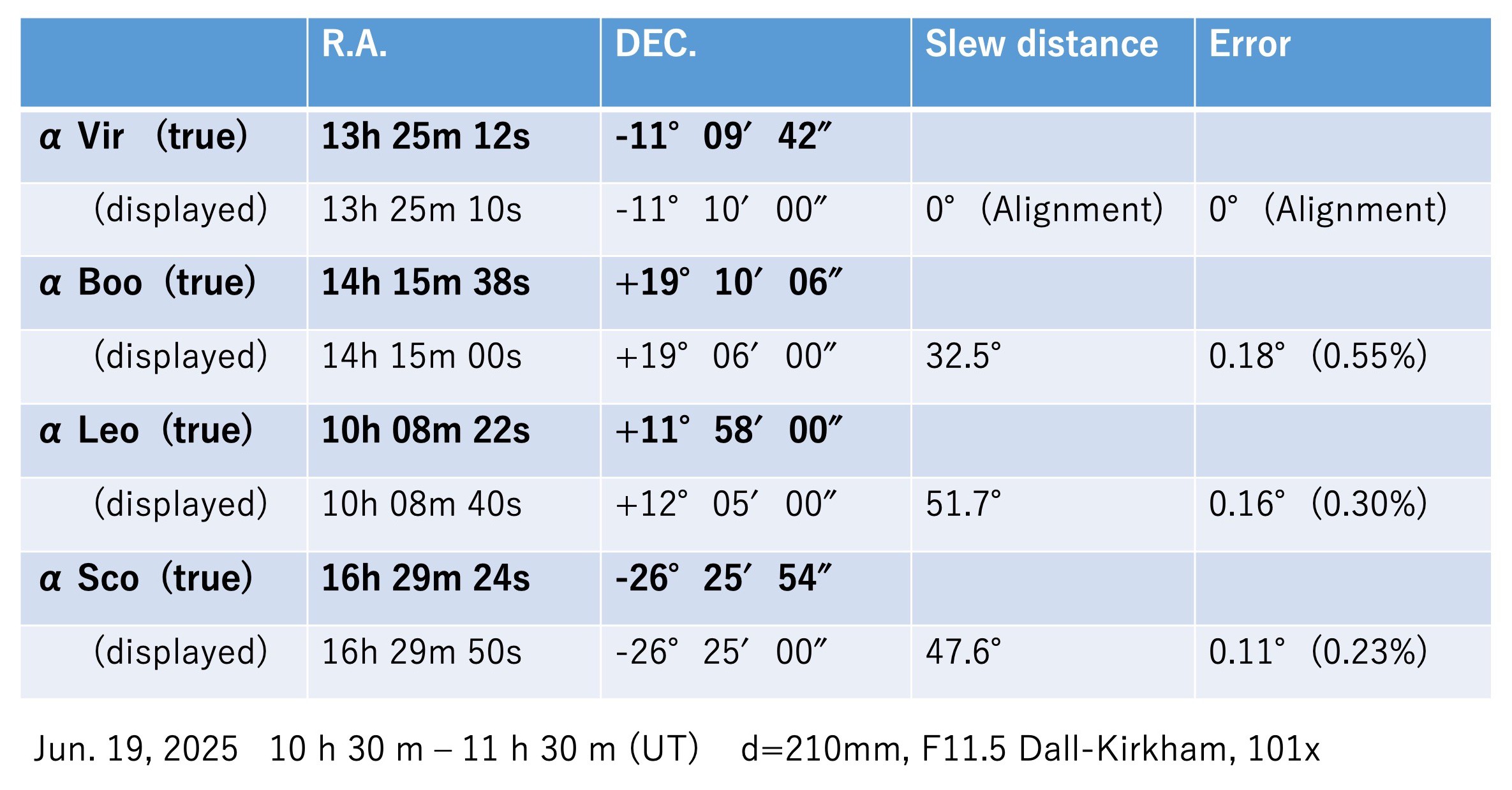
The following Table 1 shows the evaluation results of the display error of R.A. and Dec. by actually introducing fixed stars to the center of the field of view. First, Alpha Virgo (Spica) was introduced at the center of the field of view and displaying values were aligned with the true values of R.A. and Dec. The 3rd line of the table indicated the true coordinate values for R.A. & Dec of Alpha Bootis (Arcturus). The 4th line indicated the displaying values when the telescope is slewed so that Alpha Bootis is at the center of the field of view. And the ratio of the error to the amount of slewing angle is shown. The same evaluation was made for the introduction of Alpha Leo (Regulus) and Alpha Scorpius (Antares) below. Since these errors are within 0.6%, I considered the accuracy of YTM-4 as an equatorial mount to be sufficient.
Table 1 Positioning error results of YTM-4
I became possible to mount a telescope of the aperture for my planetary visual observation with a self-made equatorial mount and a computer system. I will continue to evaluate the operation of this YTM-4 system.
(Posted on May. 01, 2025)
(Latest revision on Jun. 20, 2025)