Peter McCloud
The Briggs and Stratton engine used on #Goliath - A Gas Powered Quadcopter utilizes a magnet on the flywheel to trigger the ignition coils. This magnet will be utilized for measuring the engine RPM with a hall effect sensor under the engine cover.
Hardware
The Pixhawk board has six auxiliary pins that can be configured as pulse width modulation (PWM) or General Purpose Input/Output (GPIO). In GPIO mode the AUX pins can be used for measuring frequency. Unfortunately the AUX pins have to be all PWM or all GPIO and can't be a mix. Since some of the AUX pins are being used for servos, this means they can't be used for frequency detection. Additionally the analog to digital (ADC) ports don't have interrupt capability, meaning that they can't be used for frequency measurement either.
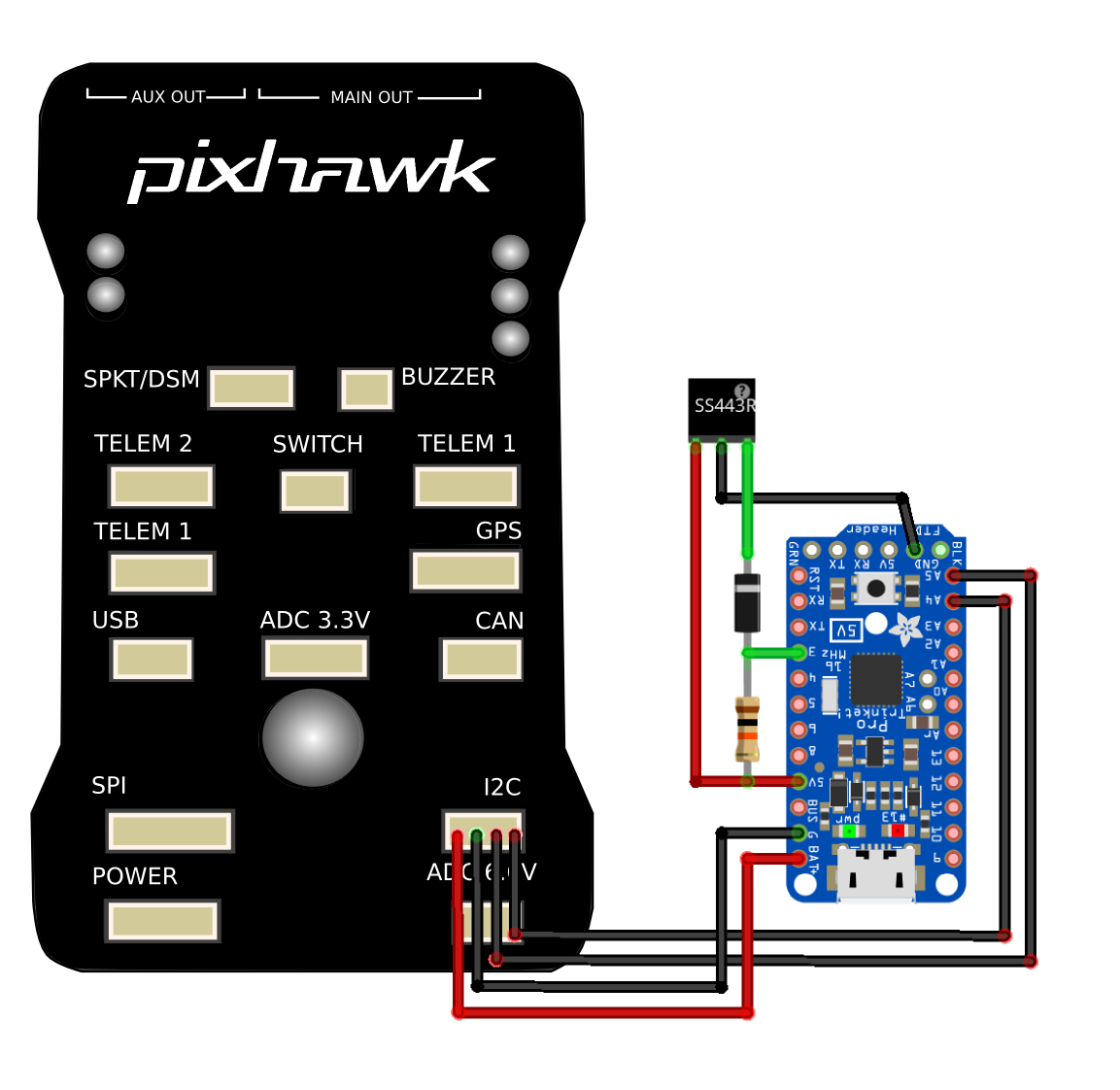
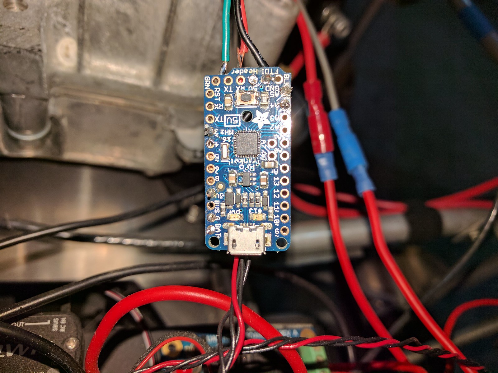
This means that for the current application, an off-board frequency measurement option is needed. An Arduino will be connected to the hall effect sensor to measure the frequency. The frequency data will then be based to the Pixhawk via I2C. A 5V Trinket Pro was selected to it's small size. A sketch of the circuit is shown below.
Software
Arduinio Sketch for Trinket Pro
https://github.com/mccloudaero/goliath-quadcopter/tree/master/avionics/rpm
 The hall effect sensor is a uni-polar sensor meaning that the sensor only gets triggered by a specific orientation to a magnetic field. For this case the back of the sensor case has to be facing the flywheel magnet.
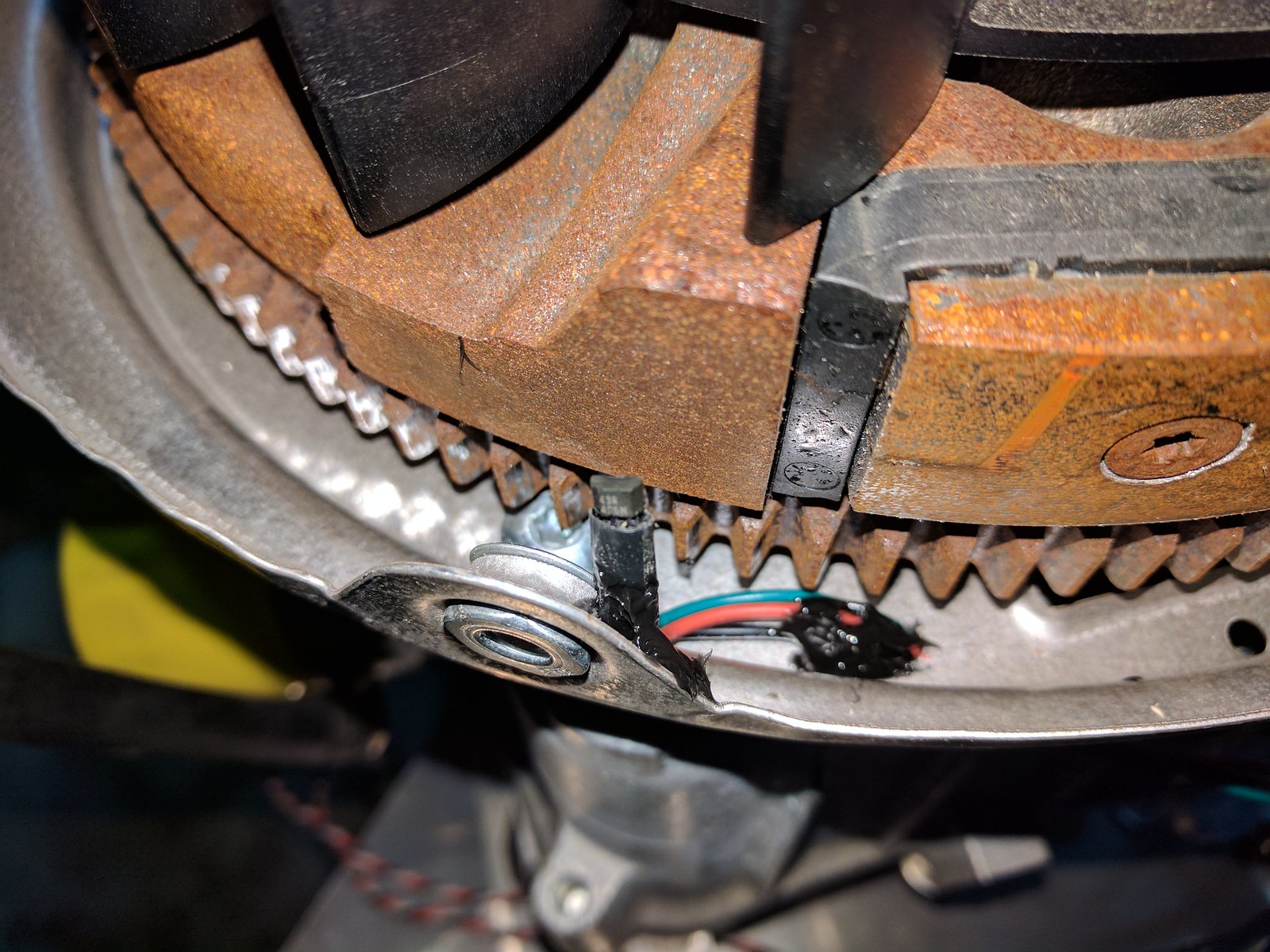 The sensor was also re-positioned to be level with the middle of the magnet.
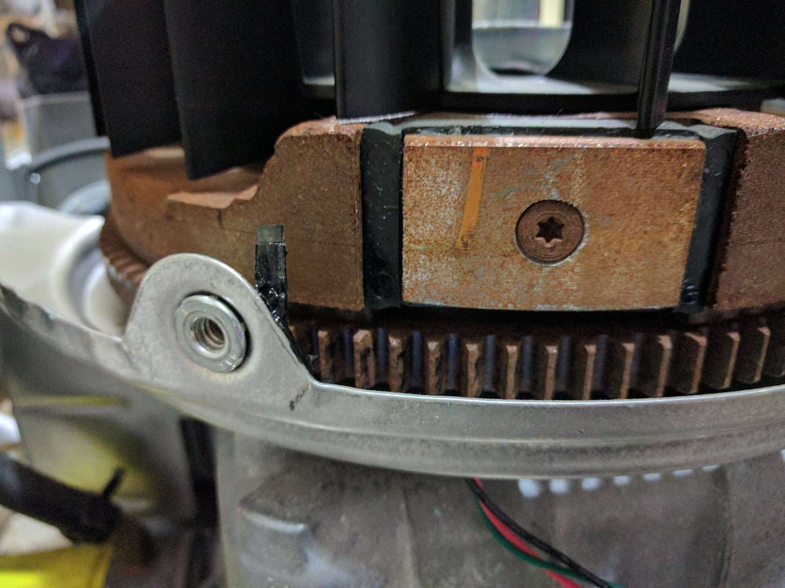 A quick test of the setup was done to make sure the electronics work. The arduino was configured to blink the on-board LED when the magnet was detected. Then the engine was spun by hand to pass the magnet by the sensor. The arduino correctly detected the magnet and flashed the LED each time the magnet passed by.
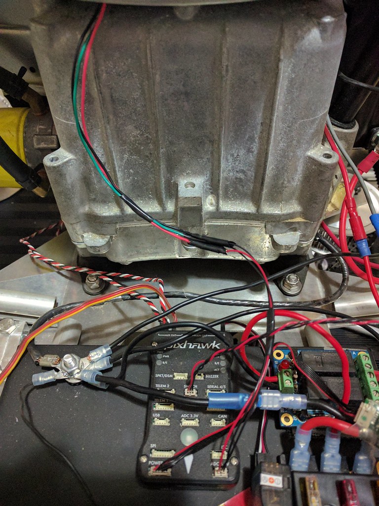
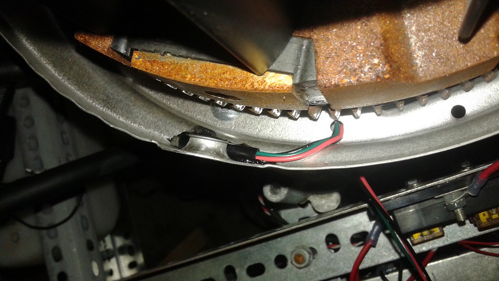 Today the sensor was connected to the Pixhawk ADC port. The wire leads were spliced onto 3 pin Hirose connector and a 10k resistor was added between the power and signal lines.