 Yann Guidon / YGDES
The TT IHP26a experience has taugh valuable lessons...
One of them is the need to transmit data reliably with few pins at high speed and efficiently yet easily/simply.
I'd like to have a 6-pin "link" interface à la SHARC but it does not look possible or at least practical, 6 is too tight. But 7 or 8 looks good.
For comparison, RGMII uses 6 signals in each direction (source clocking included) plus 2 config pins (MDC/MDIO) for a total of 14.
But I'm also throwing some TMPI in the lot to reduce power draw and EMI so that's one more pin.
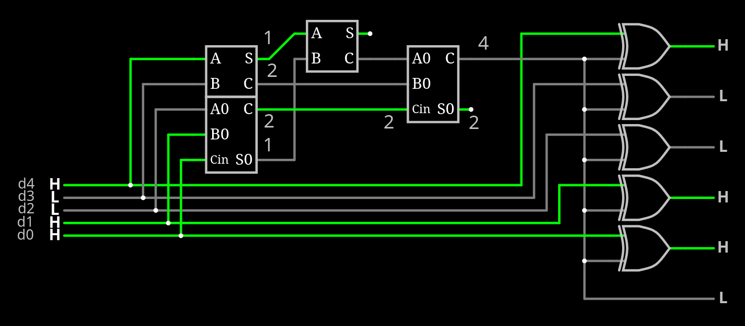
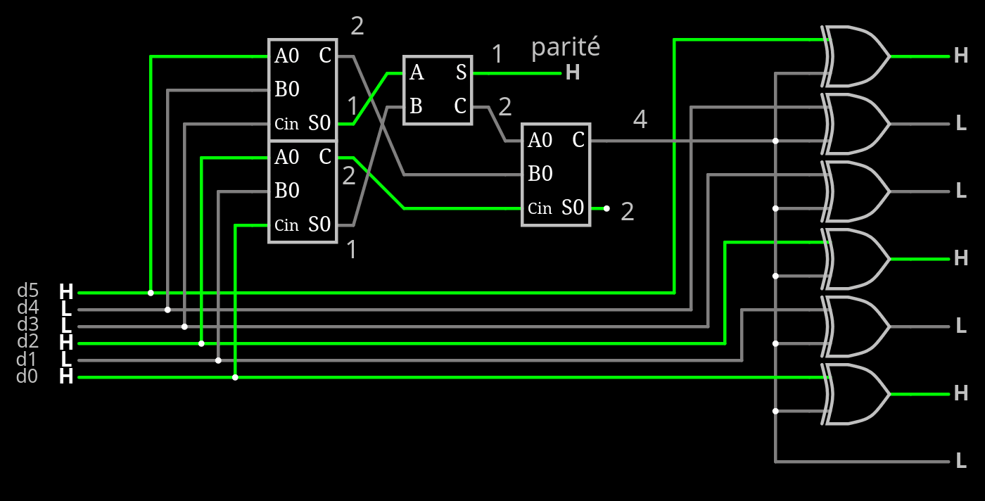
I have come up with this 5-bit popcount
The argument being :
- 18 bits of data (16+C/D+parity)
- 2 bits of link status (Quiet/Synching/Idle/Data)
that's 20 bits = 5×4
5 being odd, it's not considered at the number of words, however 4 is perfect.
So we get 5 bits of data, plus 1 bit of TMPI and 2 bits of staggered/4-phase clock, to keep transitions low.
There would be a TMPI-AC: it's a time-differential transition minimisation so we need to "clear" the initial value. This is done by the clock signals that do not complete a full 4-phase cycle, just doing a pulse with all-0s (or something).
.
(state machine diagram here)
00 => 01 => 00 : clear the ACcumulator
00 => 01 => 11 => 10 => 00 : data without inversion
00 => 10 => 11 => 01 => 00 : data with inversion
.
With 4-phase signals, there is the potential of transmitting another bit by changing the phase / swapping the signal that sends the first rising edge => this can encode a 2nd-level TMPS bit, for extra-lower power draw.
So it is actually transmitting 21 bits over 8 wires in 4 cycles, which is 21/32 of efficiency but with much fewer transitions.
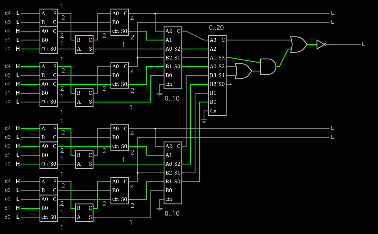
Now there is the challenge of designing a 20-bit popcount.
Maybe I could even drop the 5-bit popcount that adds another wire but it's too easy/alluring to pass... Saving one pin is great anyway, I'll have to check how it reduces power draw.
.
Just for the record here is the 6-bit TMPS circuit
...
Anyway, for that MAJ20 circuit...
I can easily have four 3-bit partial sums and they must be added together. The circuit must detect a value of 10 or more, requiring 4 bits. No need to compute the 5th bit if a custom adder is used.
...
I have not found how to combine both the word-level and quibble level TMPI. There are now 2 possibilities :
- use 7 bits per quibble with a word-level TMPI. The transition gains are low but you can't make the interface smaller.
- use 8 bits per quibble with a dedicated TMPI per quibble, providing less violent bursts of close transitions. required when EMI gets difficult.
The most attractive version at first glance would be the 7-bit version but the 8-bit version would be required for extra performance. Combining both would be rad though.
Discussions
Become a Hackaday.io Member
Create an account to leave a comment. Already have an account? Log In.