 Simon Trendel
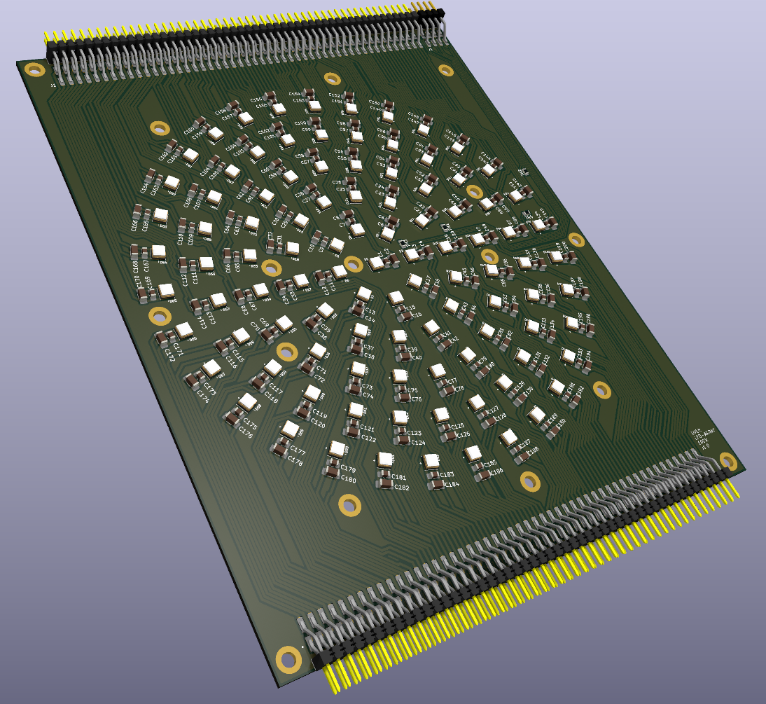
Next I designed the LED panel. We chose 100x LEDs for this version. The spacing is as uniform as possible. Unfortunately EasyEDA doesn't seem to have any way of positioning components in a programmatic way, so for this PCB I'm using KiCAD again. KiCAD has a python scripting console and I used the following script to place all the components automatically.
import math
import pcbnew

board = pcbnew.GetBoard()

# Ring configuration
rings = {
    0: 1,
    1: 8,
    2: 14,
    3: 20,
    4: 26,
    5: 31
}

ring_spacing_mm = 12
cap_spacing_mm_1 = 3.5
cap_spacing_mm_2 = 2.6
center_x_mm = 100
center_y_mm = 111
ref_offset_mm = 1.5  # tangential offset

def mm_to_nm(val):
    return int(val * 1_000_000)

center = pcbnew.VECTOR2I(mm_to_nm(center_x_mm), mm_to_nm(center_y_mm))
ref_counter = 1

for ring_index, led_count in rings.items():
    radius_mm = ring_index * ring_spacing_mm

    for i in range(led_count):
        angle_rad = -2 * math.pi * i / led_count
        angle_deg = -math.degrees(angle_rad)

        dx = math.cos(angle_rad)
        dy = math.sin(angle_rad)
        tangent_dx = -dy
        tangent_dy = dx

        # LED
        led_ref = f"D{ref_counter}"
        r_led = radius_mm
        led_pos = pcbnew.VECTOR2I(
            center.x + mm_to_nm(r_led * dx),
            center.y + mm_to_nm(r_led * dy)
        )
        led_fp = board.FindFootprintByReference(led_ref)
        if led_fp:
            led_fp.SetPosition(led_pos)
            led_fp.SetOrientationDegrees(angle_deg - 90)
            c1_txt = c1_fp.Reference()
            c1_txt.SetVisible(True)
            c1_txt.SetTextAngleDegrees(0)
            c1_txt.SetPosition(pcbnew.VECTOR2I(
                c1_pos.x + mm_to_nm(0),
                c1_pos.y + mm_to_nm(0)
            ))

        # Capacitor 1
        c1_ref = f"C{2 * (ref_counter - 1) + 1}"
        r_c1 = r_led + cap_spacing_mm_1
        c1_pos = pcbnew.VECTOR2I(
            center.x + mm_to_nm(r_c1 * dx),
            center.y + mm_to_nm(r_c1 * dy)
        )
        c1_fp = board.FindFootprintByReference(c1_ref)
        if c1_fp:
            c1_fp.SetPosition(c1_pos)
            c1_fp.SetOrientationDegrees(angle_deg + 90)
            c1_txt = c1_fp.Reference()
            c1_txt.SetVisible(True)
            c1_txt.SetTextAngleDegrees(0)
            c1_txt.SetPosition(pcbnew.VECTOR2I(
                c1_pos.x + mm_to_nm(0),
                c1_pos.y + mm_to_nm(0)
            ))

        # Capacitor 2
        c2_ref = f"C{2 * (ref_counter - 1) + 2}"
        r_c2 = r_c1 + cap_spacing_mm_2
        c2_pos = pcbnew.VECTOR2I(
            center.x + mm_to_nm(r_c2 * dx),
            center.y + mm_to_nm(r_c2 * dy)
        )
        c2_fp = board.FindFootprintByReference(c2_ref)
        if c2_fp:
            c2_fp.SetPosition(c2_pos)
            c2_fp.SetOrientationDegrees(angle_deg + 90)
            c2_txt = c2_fp.Reference()
            c2_txt.SetVisible(True)
            c2_txt.SetTextAngleDegrees(0)
            c2_txt.SetPosition(pcbnew.VECTOR2I(
                c2_pos.x + mm_to_nm(0),
                c2_pos.y + mm_to_nm(0)
            ))

        ref_counter += 1

pcbnew.Refresh()
board.Save(board.GetFileName())
print("✅ Components and reference labels updated with tangential offsets.")
Routing was a bit tricky, because for a copper base board you can only route on the top of the board. I included 4 NTC thermistors as well, so we can get feedback on the LED temperature.
The LED driver boards will be connected on either side of the LED panel using the 2.54mm pin headers.
Discussions
Become a Hackaday.io Member
Create an account to leave a comment. Already have an account? Log In.