 Simon Trendel
All parts arrived and it was time to test.
All boards had mistakes :( . But all could be fixed on the PCBs.
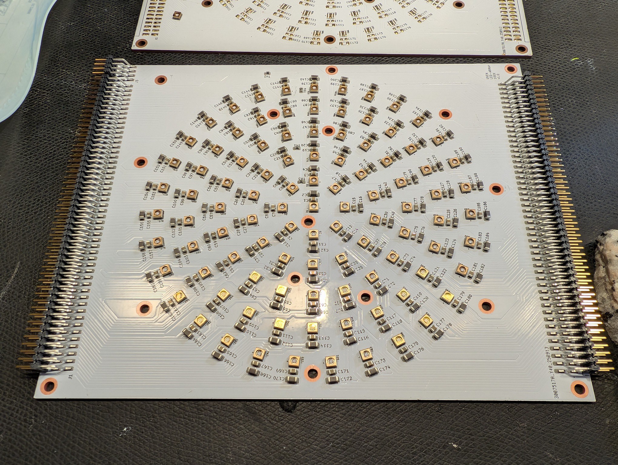
After the initial light test, I assembled one SBT-10X LED to the copper core PCB. It turned out, I had wired the driver edge connector incorrectly. Luckily the LED footprint is symmetric, so I could simply assemble the LED 180 deg rotated. I burned only two LEDs until I realized the mistake.
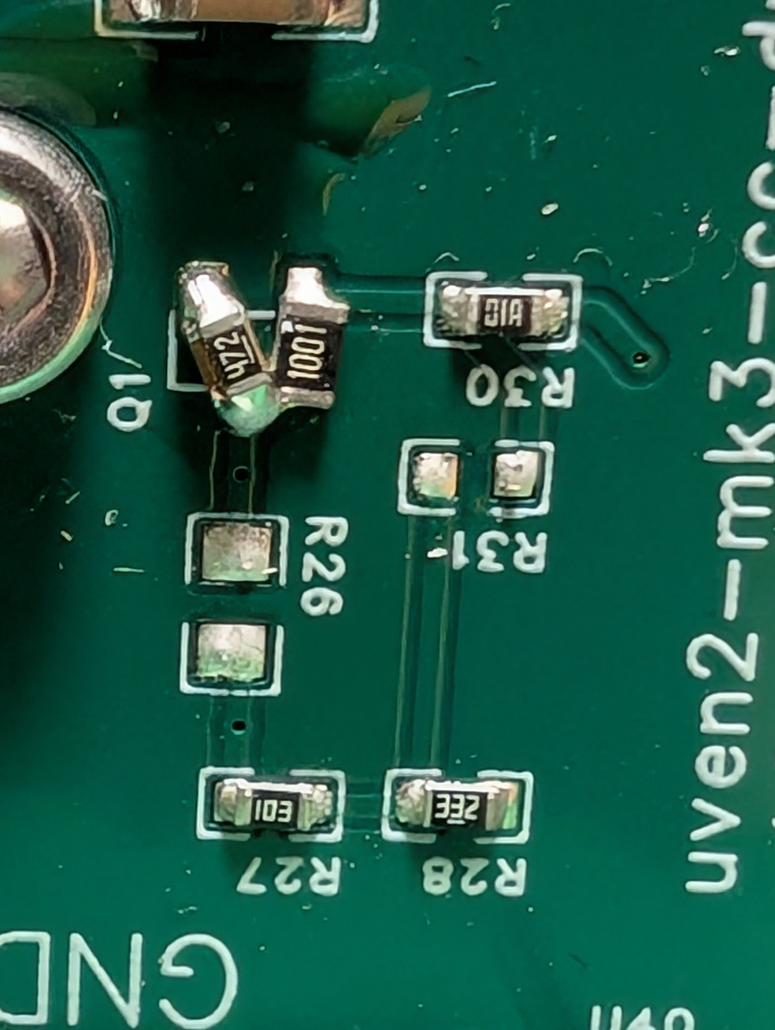
The driver PCB had another mistake that was more subtle and took a while to figure out. The mistake was to drive the CTRL pin of the led driver IC using 12V. That pin has a max voltage of 3.3V and driving it with higher voltage can damage the IC. So I removed the mosfet and pulled the CTRL pin low.
There are two mistakes on the main-board. They are both very dumb, but luckily could be fixed on the main board PCB.
The first mistake was to wire the EPAD pin of the 12V->5V and 12->3.3V DCDC converters to GND. For the fixed voltage version I assembled, this pin needs to be floating and serves as thermal heat sink. I simply cut the pins and added an external heat sink.
The second mistake was not having checked the datasheet of the heat sink fans. Turns out they draw 4A@12V, which immediately annihilated the MOSFET I had planned for them.
All mistakes are fixed in the latest version on github.
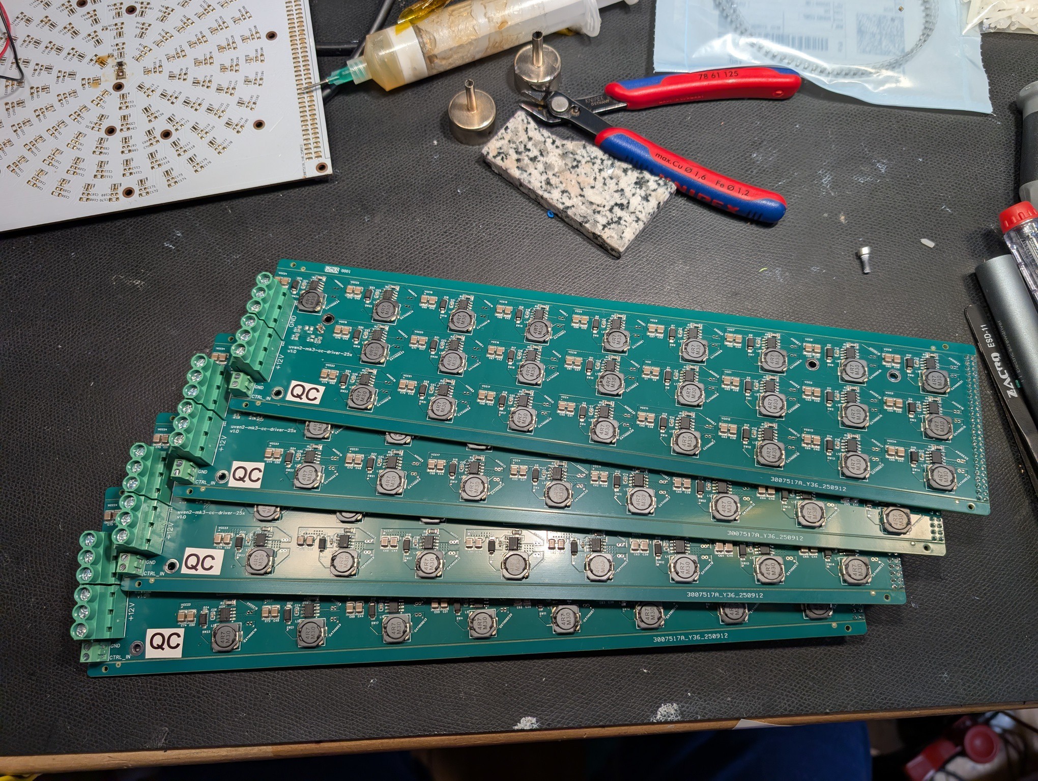
I fixed all drivers and tested all channels of each driver.
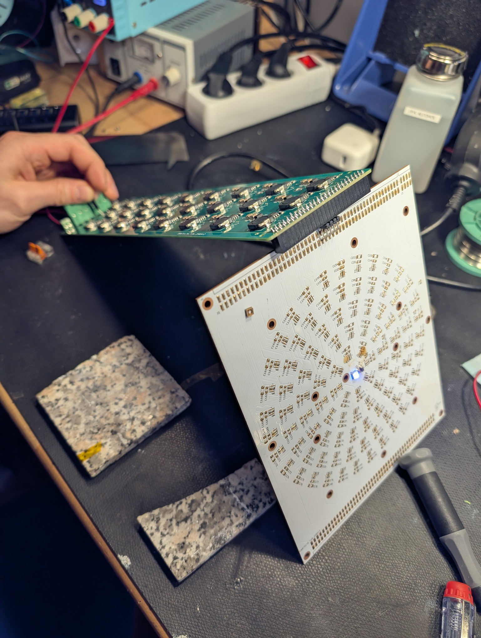
Next I assembled the full LED panel (with the LEDs rotated 180deg)
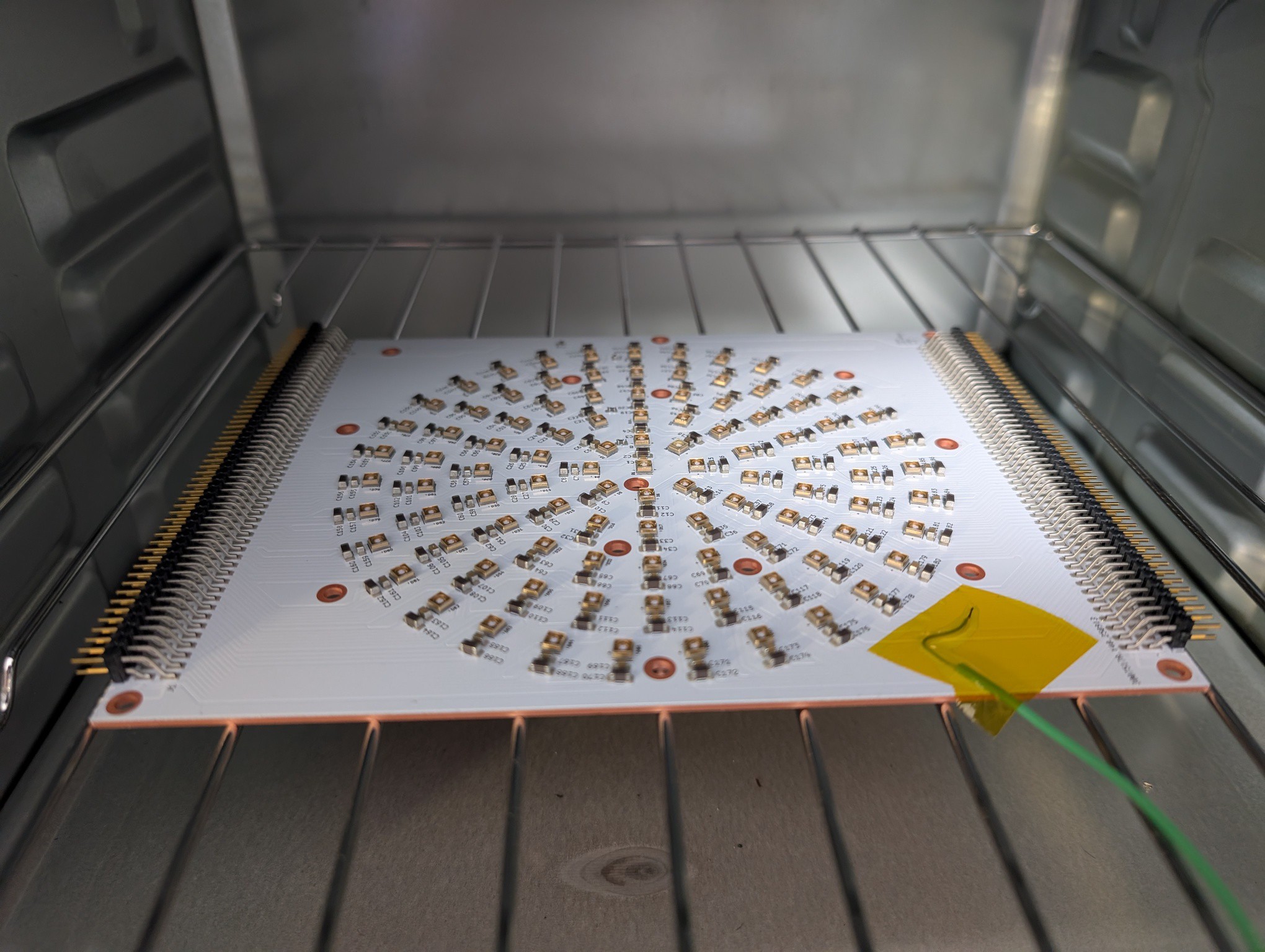
For testing the full panel I needed to assemble the rest of the lamp.
Discussions
Become a Hackaday.io Member
Create an account to leave a comment. Already have an account? Log In.