 Pablo
PabloThe eInk Badge is an open-source, low-power electronic badge built around the Raspberry Pi RP2040 and a 2.9" four-color E Ink display. Designed with customization and flexibility in mind, it’s ideal for hackers and tinkerers who want to build a dynamic, always-on display without worrying about battery life.
Main Controller
At the heart of the eInk Badge is the RP2040, a powerful and energy-efficient microcontroller developed by Raspberry Pi. Featuring a dual-core ARM Cortex-M0+ processor, it delivers solid performance for a wide range of embedded applications—from interactive wearables to responsive control systems.
Core highlights include:
-
Dual-core ARM Cortex-M0+ running up to 133 MHz – enables multitasking and efficient code execution
-
264 KB of internal SRAM and support for external QSPI flash – plenty of memory for most projects
-
Versatile I/O options – includes 2× UART, 2× SPI, 2× I²C, 16× PWM channels, 3× ADC inputs, and up to 30 GPIO pins
-
Programmable I/O (PIO) – lets you create custom hardware interfaces in software
-
USB 1.1 host/device support – native USB for data or programming
-
Low-power 40 nm architecture – optimized for battery-powered and portable systems
-
Drag-and-drop USB bootloader – makes flashing firmware simple and fast
-
Broad language and ecosystem support – works with C/C++, MicroPython, CircuitPython, Rust, and others
eInk Display
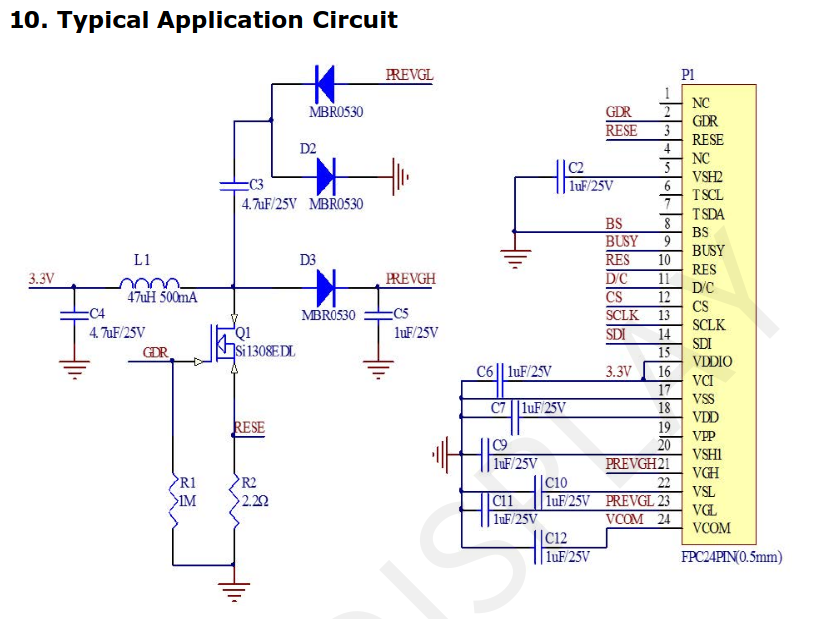
The eInk Badge features the GDEY029F51 as its primary display—a 2.9-inch four-color E Ink panel with a resolution of 296×128 pixels. This display is driven by the JD79661 controller and uses an SPI interface for communication, making it easy to integrate with microcontrollers like the RP2040.
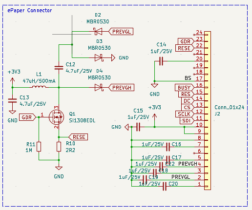
The module supports four distinct display colors (black, white, red, and yellow), allowing for eye-catching visuals even in low-power applications. For electrical connections and proper integration, a recommended circuit is provided in the manufacturer’s datasheet.
Notice that, even I used this display model, the eInk badge is compatible with many different eINk badges from Good Display, so you just need to acquire the one you need, and change the code according the display used.
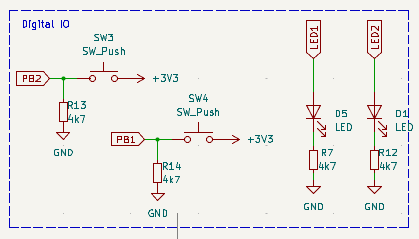
Schematics
The main controller is a RP2040. The program is sent to the microcontroller using an USB-C, in which only the USB2.0 pins are used.
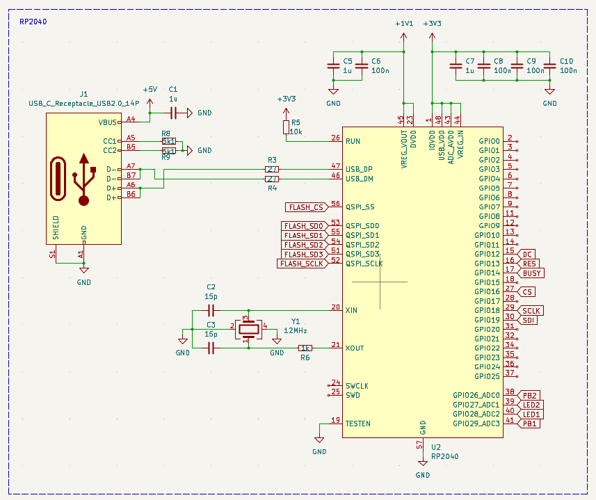
To function properly, the RP2040 requires a 12 MHz external crystal oscillator for its system clock, along with several decoupling capacitors to ensure stable power delivery.
For program storage, the RP2040 relies on an external flash memory connected via a QSPI interface. In this design, we’ve used the W25Q16, a 16 Mbit (2 MB) flash chip that offers fast and reliable access to firmware and data.
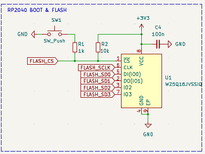
The board includes a BOOT button, which is used to place the RP2040 into USB bootloader mode—allowing you to easily upload new firmware.
Power is supplied via the 5 V line from the USB port. A low-dropout (LDO) voltage regulator then steps this down to 3.3 V, which powers the microcontroller and all other onboard components.
Finally, the display is connected to the board using a flat-cable connector. The circuit used is provided by the vendor.
In addition, 2 push buttons and 2 leds are added to the board.
Firmware & Display Control
The firmware for the eInk Badge is developed using the Arduino IDE, making it easy to modify and upload new features. For handling the E Ink display, we use the GxEPD2 library—a powerful and flexible tool designed specifically for SPI-based e-paper displays.
GxEPD2 supports a wide variety of displays from vendors like Waveshare and Good Display, and it's optimized to run efficiently on microcontrollers such as the RP2040, ESP32, and STM32.
The library offers a straightforward, high-level API for tasks like initializing the display, drawing graphics or text, refreshing the screen, and managing power consumption—making it ideal for low-power, battery-operated projects...
Read more »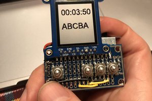

 Manuel Tosone
 Jara
Jara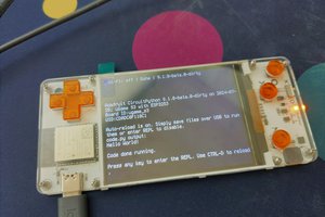
 deʃhipu