ryan5836600
Overview Demonstration
AI Dog Detection
Pinch Detection
Fail Safe Mechanism
In order to do this demonstration I had to temporarily disable the pinch detection by reflashing the ESP32 with a firmware that allowed setting the closing current limit very high.
Outside Bark Detector
Safety first!
These are 6 layers of safety that have been implemented.
- The Home Assistant server will not send the close door command if the Frigate NVR AI object detection system detects that there is a dog, cat, or person in the “pinch zone”
- The main motor controller self checks the current sensor each time the close command is received and if it detects an anomaly it aborts the closing operation
- If the closing current threshold is exceeded (pinch detection) the closing operation is aborted and the door fully opens
- If all the above fails the soft TPU compliant clevis that connects the actuator rod to the door panel will disconnect
- If all the above fails there is a TPU shear pin connecting the actuator to the top clevis that will disconnect.
- If all the above fails there is a PTC resettable fuse that will reset the motor controller. Upon bootup the motor controller firmware defaults to opening the door as soon as boot up is complete
Mechanical
The first decision is deciding where to put the door, either through a wall or retrofitting an existing opening. I bought this PetSafe Extreme Weather Sliding Glass Pet Door because I originally hoped to be able to teach my dog to use the flap, that didn’t work out. This insert is expensive however it is well made and conveniently the integrated steel track intended for inserting the rigid plastic security panel works perfectly for mounting an improved motorized panel.
The new panel started out as a sheet of HDPE 12” x 24”. HDPE is great because it has low friction which is required to slide freely in steel track. I used a table router to reduce the thickness of outside tabs of the sheet until the fit in the track snug (less air drafts) but not too snug that it couldn’t be easily moved by hand.
The linear actuator model is JQDML 16"/400mm Stroke DC 12V Linear Actuator 66lbs/300N Speed 1.77"/sec. This model was selected because it was geared for highest speed lowest force which is the preference for this application. Unfortunately, this actuator is only a two wire model with no feedback. Frustratingly it does have limit switches, they are just not exposed in a way that you can use them out of the box. I learned that what it does is pair the limit switches with diodes in this clever arrangement that automatically stops the current flow at either end until the polarity of the supply is reversed.
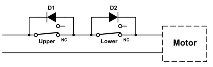
That arrangement was no good for me because I wanted to at least have retracted/extended (open/close) feedback from the limit switches. So I disassembled and rewired the actuator with new 5 wire jacketed cable (MTR1, MTR2, GND, LIMIT_UPPER, LIMIT_LOWER) with the intention of attaching the one side of the limit switches to GND and the other to side to GPIO’s with pull-up resistors. The disassembly and rewiring was not so easy and I might recommend externally mounted hall effect sensors instead.
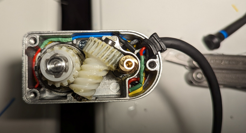
The linear actuator comes with two steel clevis and 5mm shear pins. These are way too strong for this application. I drilled holes and attached the top clevis with rivets. I 3D printed a TPU shear pin because I found it dampened the motor vibration so that there was less noise.
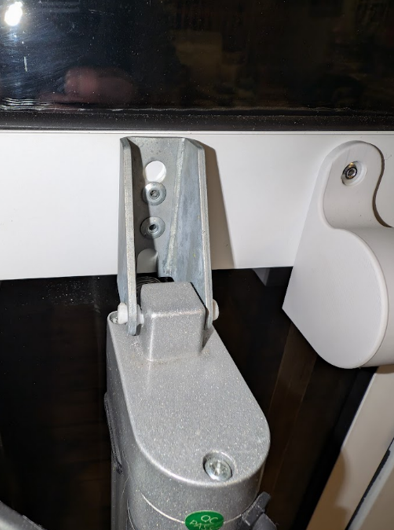
I discarded the other steel clevis and instead designed a new compliant TPU one with a fail safe overload feature. Instead of the 5mm steel shear pin I drilled the hole actuator rod larger and then tapped it for M6 and then installed a socket head cap screw in each side.
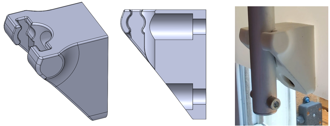
The compliant TPU clevis is not enough on its own. The issue is that once it lets go the weight of the door panel is still hard to lift. This is where the counterbalance springs come in which conceptually behave similar to a tape measure with a stronger force. The springs themselves are called constant force springs and can be purchased from Lee Spring model number LCF 250 12 075S. The spring are rated for 2.1lbs (~1kg) of force each. I found that the inside diameter of the springs fit perfectly inside a 6806-2RS bearing and then I 3D printed a housing around them by pausing the print just before the ceiling of print was to be printed and inserting the spring and bearing and then restarting the print.
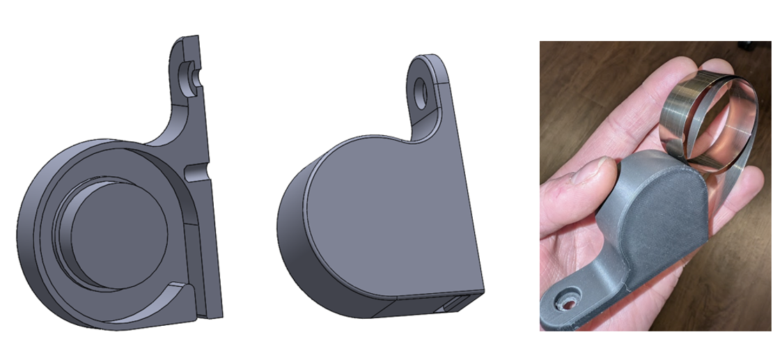
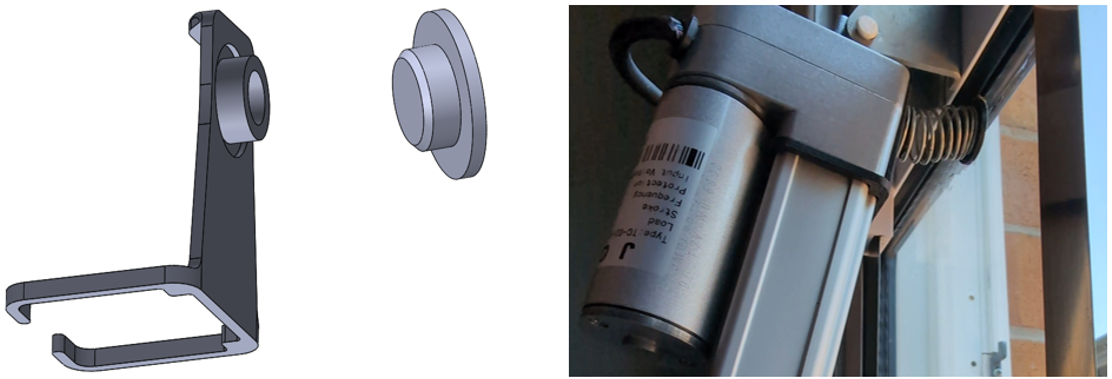
Even when the load is removed from the door panel by the compliant TPU clevis and the weight of the panel is lessened by the counterbalance springs there is still the risk of the actuator rod force itself doing harm. To reduce this risk another 2 parts were 3D printed with CF-PA to hold a coil spring that tilts the actuator rod out of the way as soon the clevis joint disconnects.
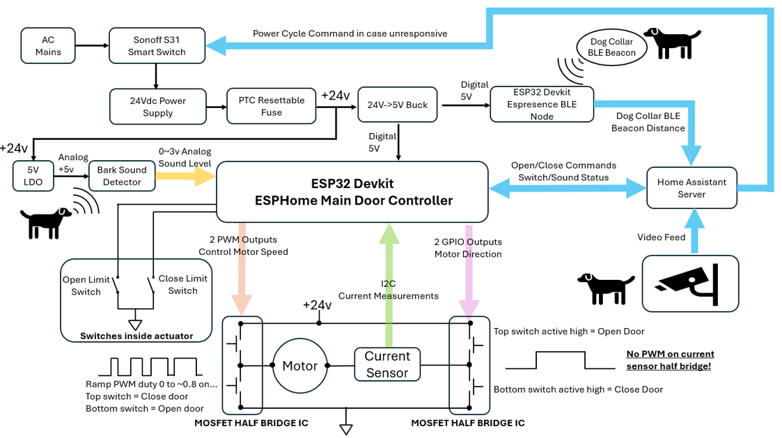
Control Architecture:
Note that the Bluetooth (BLE) aspect is for extra redundancy but is not needed.
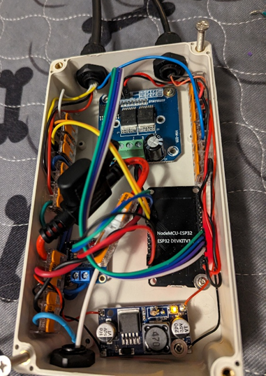
Main Controller Electronics v1: Bunch of off the shelf parts
The first version of the electronics consisted of a bunch of standalone evaluation board wired together.
- Motor Drive Module Board Module, Double BTS7960
- Adafruit 4226 INA260 Voltage/Current/Power I2C Sensor
- LM2596 DC-DC Buck Converter Step Down Module
- NodeMCU-32S ESP32 DEVKIT ESP-WROOM-32 Development Board
- Facmogu 24V 6A Power Adapter AC 100-220V
- DAOKI Electronic Project Box 158 x 90 x 60 mm+ PG7 Cable Gland
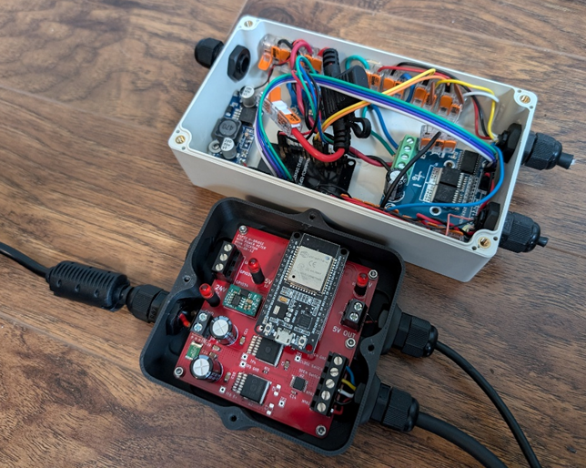
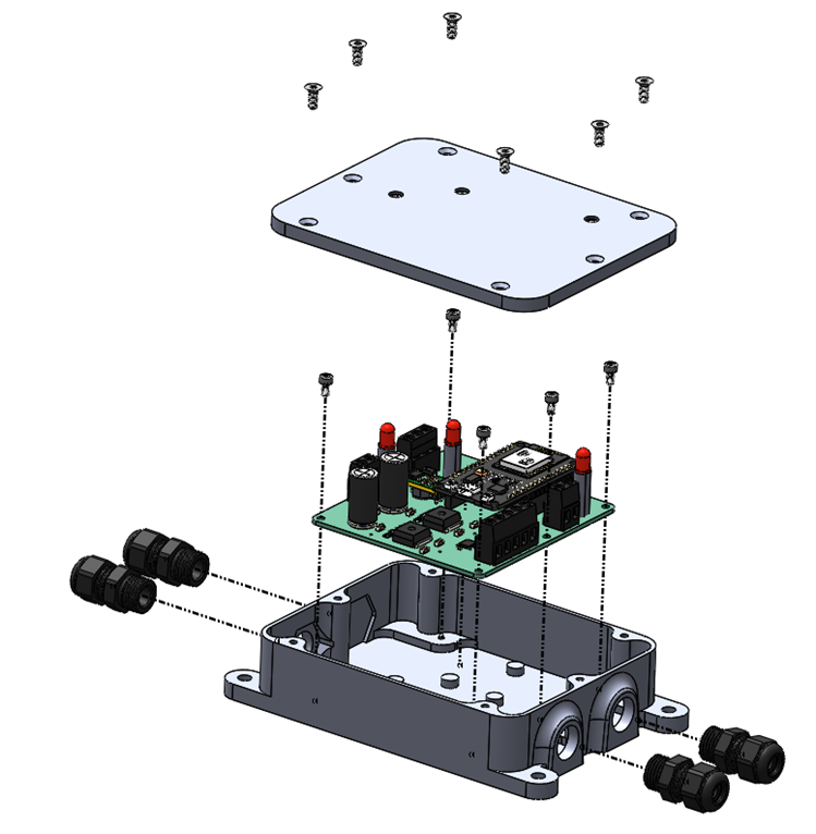
Main Controller Electronics v2: Custom PCB
Electronics v1 worked great until one day I was messing with the wires in order to replace the 19V power supply I had been using with a 24V. After that I started having I2C communication issues with the current sensor which after debugging for a while turned out to be a bad connection. This gave me motivation to learn KiCAD and design my first ever PCB to clean up the wiring.
See the KiCAD project file for more information.
Bark Detector:
SparkFun Sound Detector SKU: SEN-12642
Modifications:
1.) Change R11 from 100k to 12k to change schimtch trigger threshold from .16V to 1V
2.) Change R9 from 10k to 1Meg so that decay of vout is much slower
3.) R3 from 100k to 560k to increase gain of preamp
4.) Change R16 from 2.2k to 560ohm to make LED brighter
5.) Changed c2 from 10uF to 2.2uF to better block low freq signals
6.) Changed R8 from 100 ohm to 1k to better reject quick pulses
7.) Mic capsule died after a few weeks (water damage?) Replaced Mic, had to decrease R1 from 2.2k to 1k and put 2.7k accross the mic to adjust DC bias voltage to 3.3V
The SparkFun Sound detector is very sensitive to power supply noise so I ran 24V to it and then installed a 5V LDO on the back with some ceramic caps as recommended on the LDO datasheet.
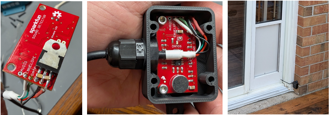
Camera:
I camera I used is IPC-T24IR-AS 3.6MM S2. It is blocked from accessing the internet. It only talks to the Frigate NVR add-on running on my Home Assistant server.
My Frigate NVR is using the Google Coral USB Accelerator (Tensor Processing Unit) to reduce Home Assistant Server CPU power consumption.
Software:
1.) ESPHome firmware on ESP32 main controller, see: doggy-door-controller-2025-06-10.yaml
2.) Home Assistant:
3.) Frigate NVR add-on for Home Assistant
An important safety feature in the software is that ever time the close door script is called the current sensor value is first checked to see if nearly 0A current is being reported. If that check fails an error is thrown and the door will not attempt to close. If that check passes the H bridge is enabled for 1500ms and then the current is checked again to ensure that it has in fact risen to >0.5A. If it has not it is assumed that the current sensor is not reporting correctly and the close process is aborted.
The close current limit is adaptive. Every time there is a successful close the limit is reduced by 10mA for the next time. If the current limit is exceeded the closing is aborted and the current limit is increased by 100mA. This way if there is ice making it difficult to close the door it will keep trying over and over with slightly higher force each time (up to a maximum of 1.9A.
Similar the bark sound threshold is also adaptive. If it happens to be really windy outside and frequently triggering the threshold the threshold adapts to a higher value so that nuisance opens don’t keep occurring. There is a slow cooldown period where the threshold will drop back to it’s resting minimum value over the course of ~1 hour.
Another important feature is the ramping PWM duty cycle. This has many benefits:
1.) Reduced inrush current decreases need for robust power supply
2.) Can use nearly the full 24V bus voltage once up to speed to make a 12V actuator go really fast.
3.) Ramp down duty cycle near the top and bottom of the actuator to gently touch the limit switches and reduce risk of blasting past them.
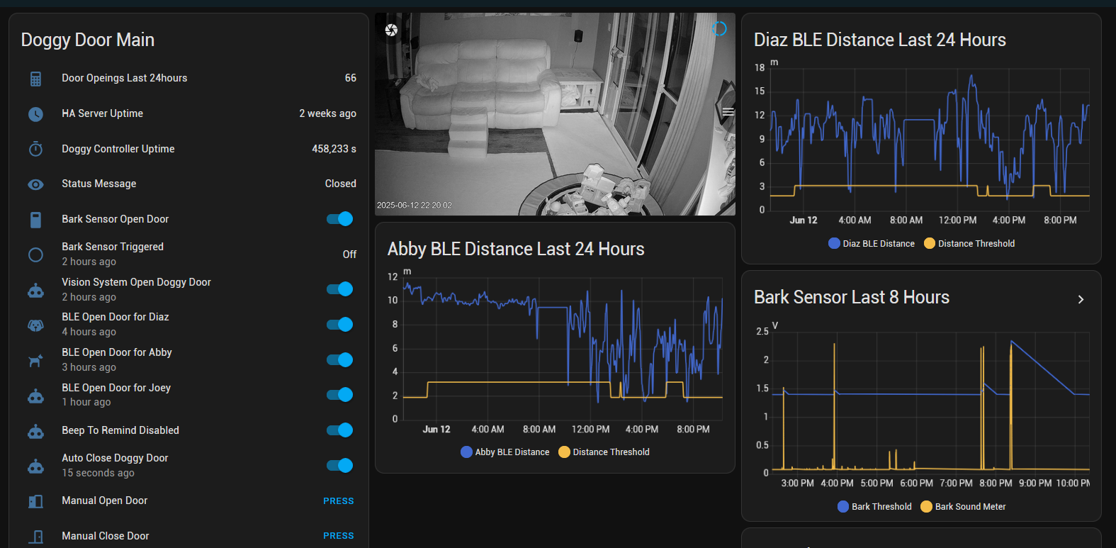
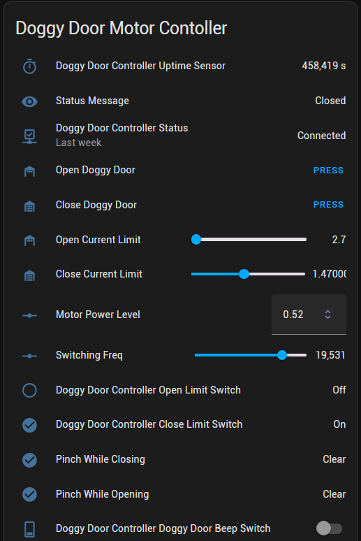
Home Assistant Dashboards: