 Christian
Conway's Game of Life is a cellular automaton devised by the British mathematician John Horton Conway in 1970.
The universe of the Game of Life is an infinite, two-dimensional orthogonal grid of square cells, each of which is in one of two possible states, live or dead.
At each step in time, the following transitions occur:
- Any live cell with fewer than two live neighbours dies, as if by underpopulation.
- Any live cell with two or three live neighbours lives on to the next generation.
- Any live cell with more than three live neighbours dies, as if by overpopulation.
- Any dead cell with exactly three live neighbours becomes a live cell, as if by reproduction.
- (all other cases: no change of cell state)
- The surface of a cube: an infinite, two-dimensional orthogonal grid of square cells.
https://en.wikipedia.org/wiki/Conway's_Game_of_Life
For my implementation the universe is:
- The surface of a cube: an infinite, two-dimensional orthogonal grid of square cells.
- The cube has one restriction to a flat surface: The cells at each corner of the cube each have only 7 neighbours instead of 8 for cells on the surface or at the edges.
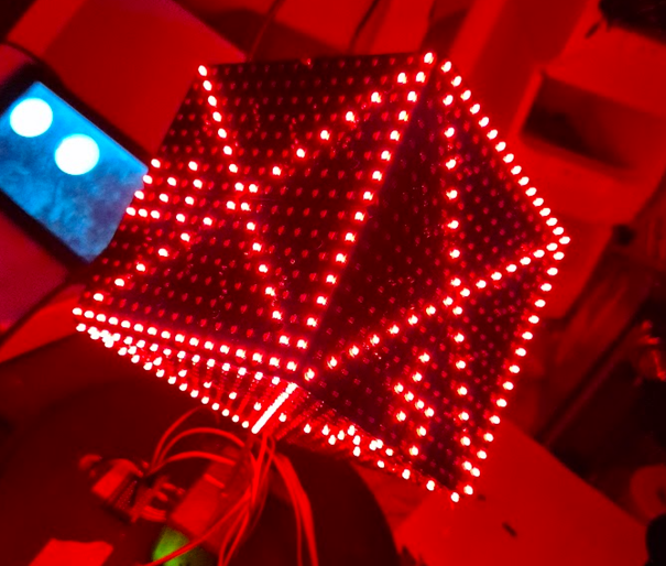
Actual Implementation
See all on my Github Repository
- Arduino UNO
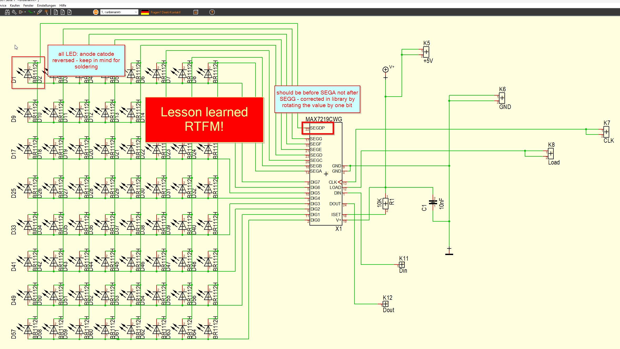
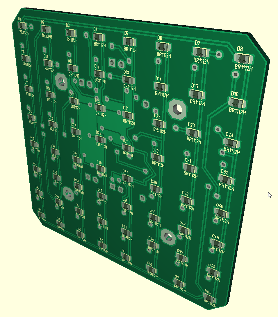
- 16x16 LED on each side = 1536 LED in total
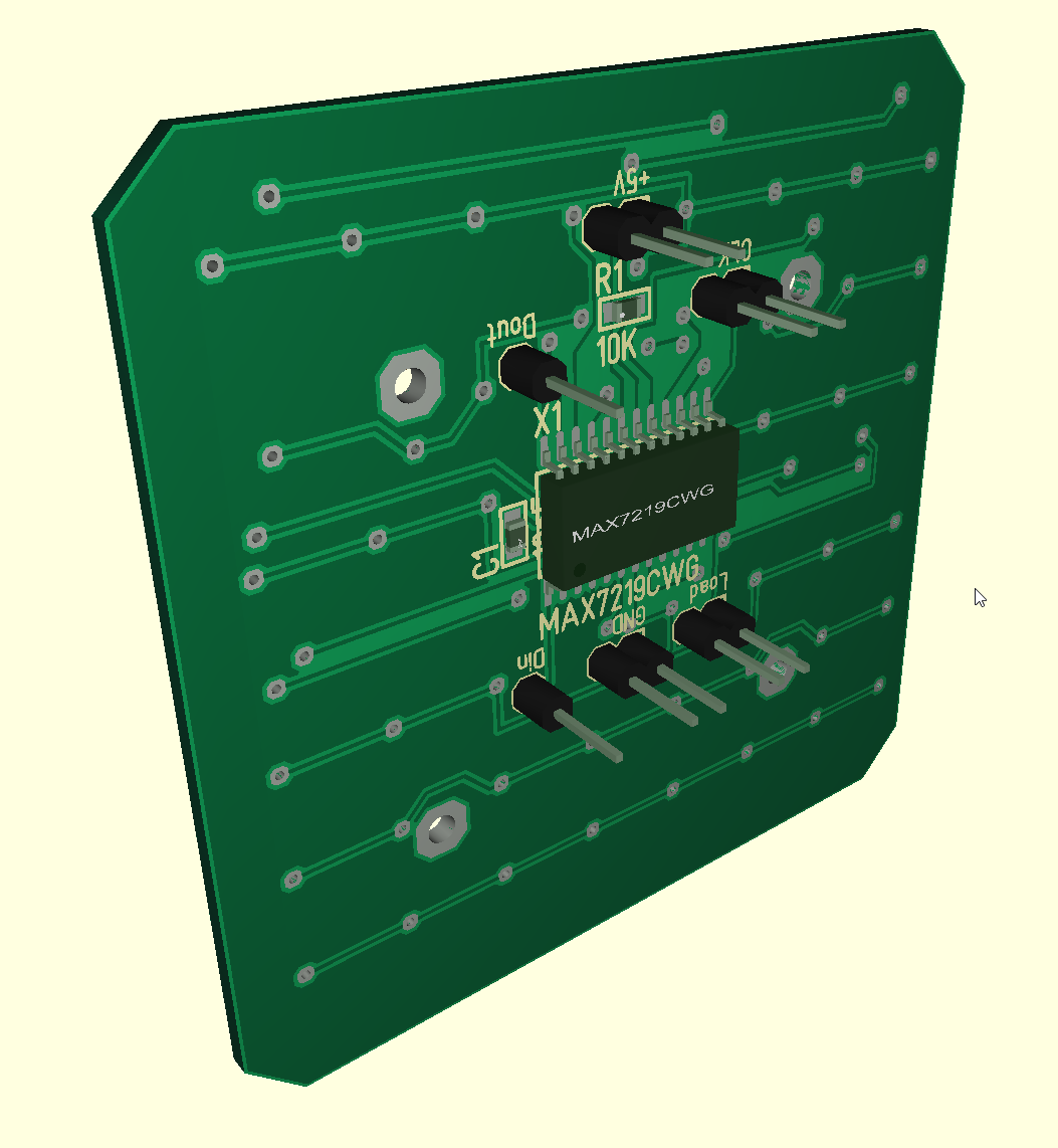
- MAX7219, daisy chained to control all LED
- Custom LED PCBs
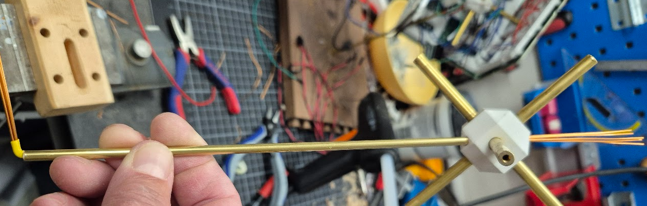
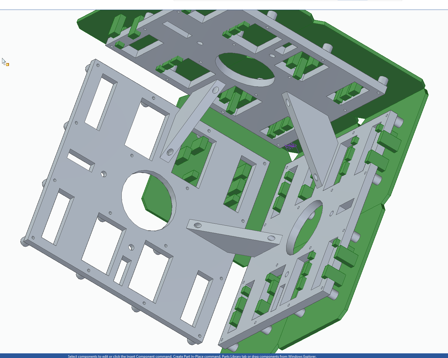
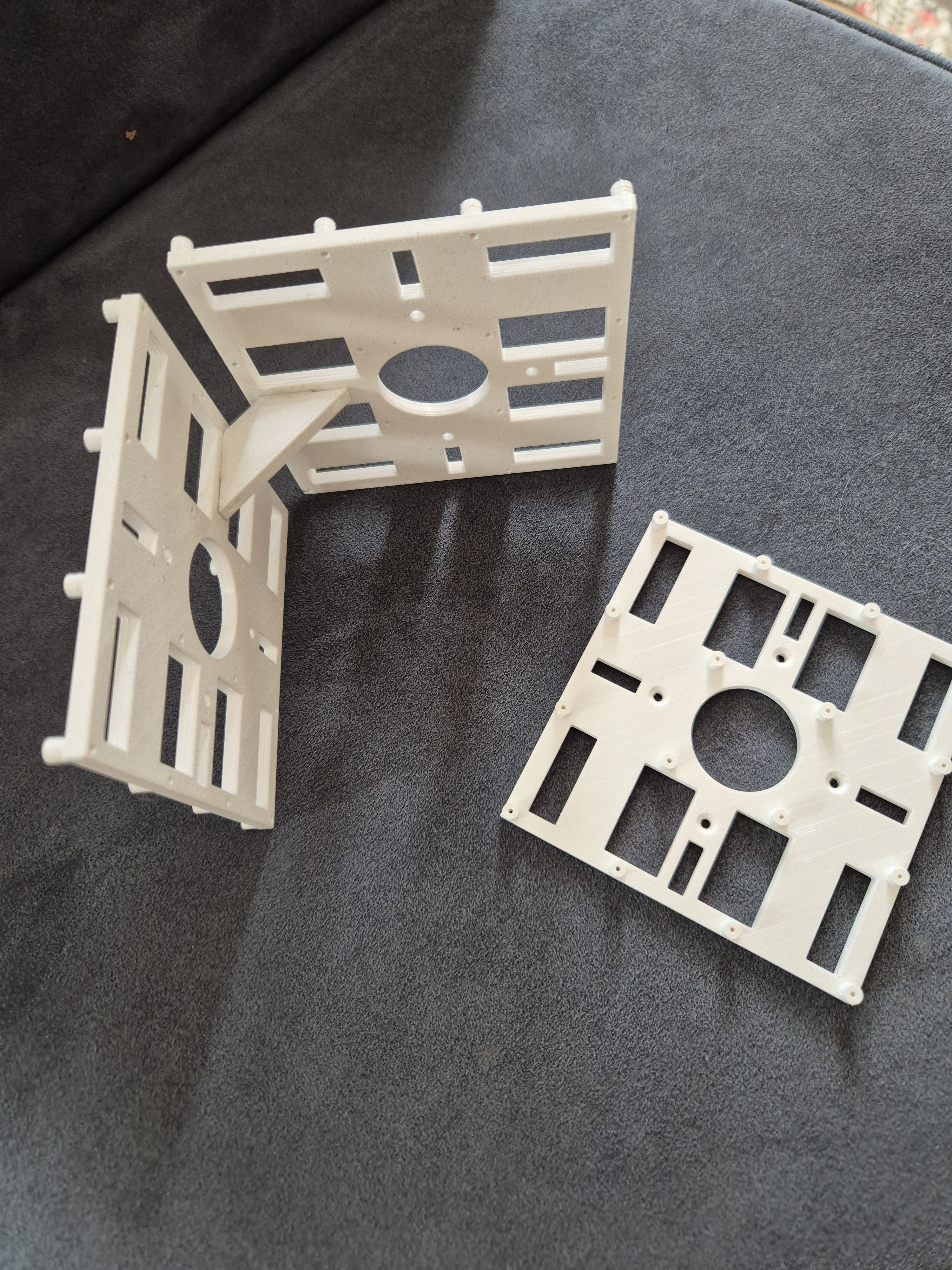
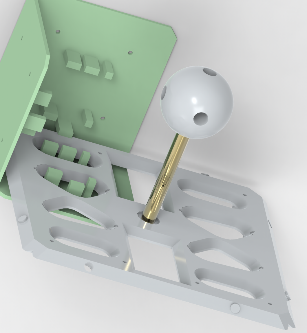
- 3D printed support structure
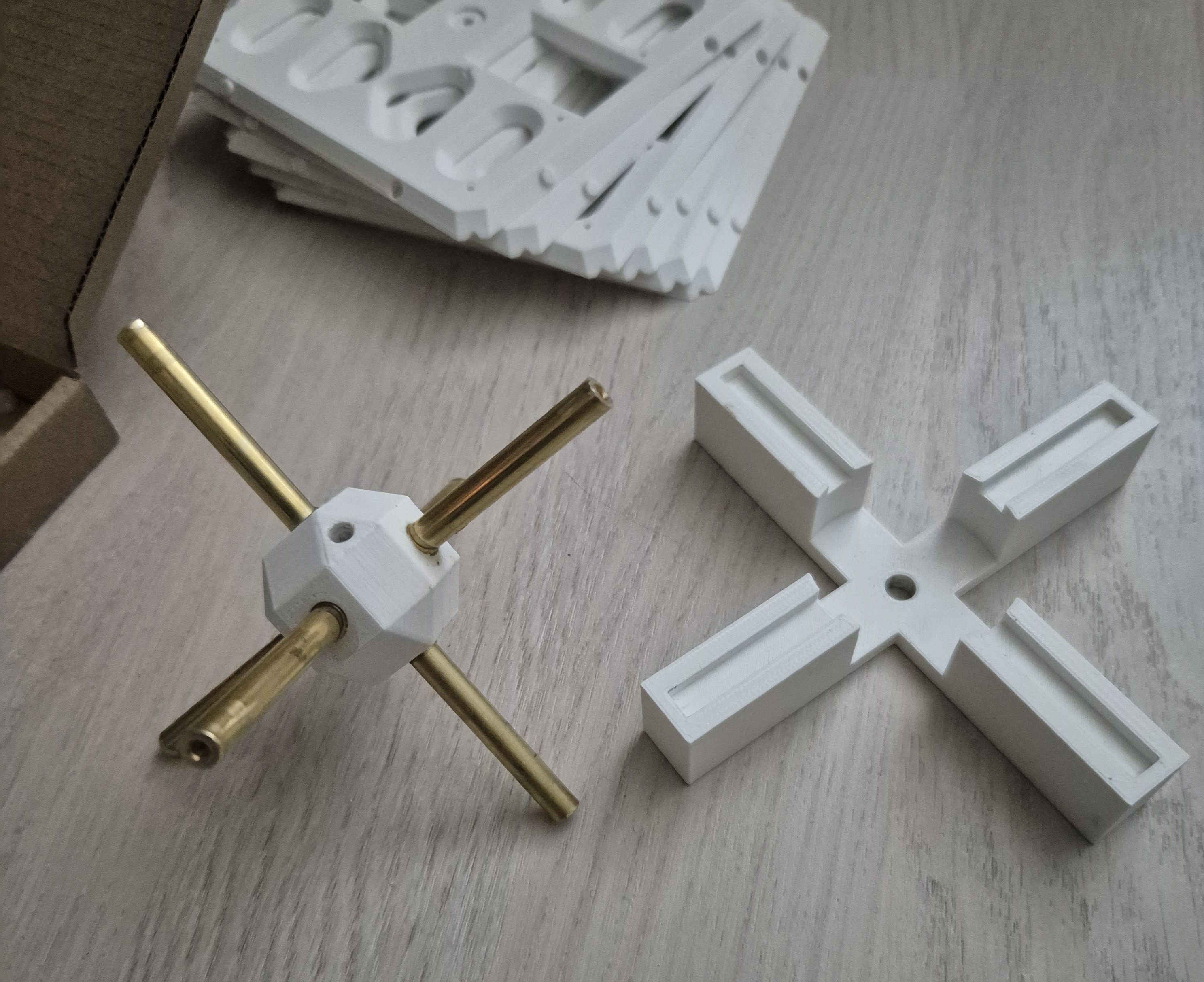
- Some brass rods for stability
- A big glass globe as dust cover

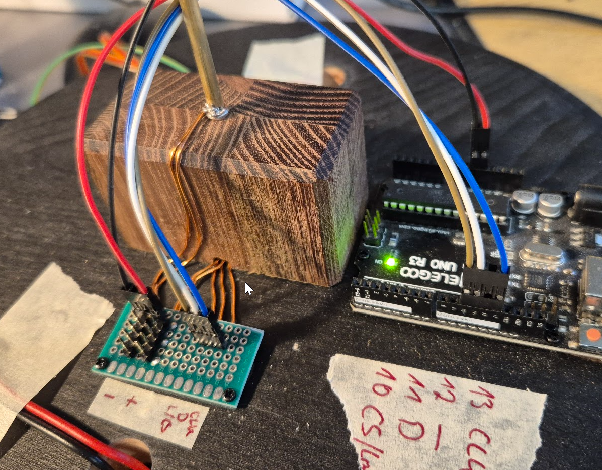
Hardware and wiring
Power supply:
- The Arduino and MAX7219 run at 5V.
- At most there are 8*24 =192 LED on. With 20mA per LED, the power supply must be able to deliver 3,84A and the wires must be able to handle that load.
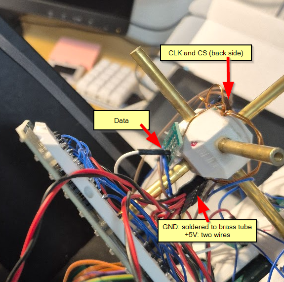
Wiring
The Arduino sits outside of the cube, 5V, GND, CS, CLK and Din are wired into to cube. Din is going through all modules as they are daisy chained. The others each have a 6pol connector in the middle of the cube (hot glued to the central cross of the support structure).
I added a few additional components:
- A potentiometer for setting the brightness
- A potentiometer for setting the initial density of the random start pattern
- A button to manually start with a new random pattern
Coordinate system
The GoL universe is a two-dimensional orthogonal grid of square cells. But on a cube surface, a “simple” x-y coordinate system does not work. And additionally, there are two coordinate systems. One describing the position of an LED on the cube and one for this LED in the chain of MAX7219 modules.
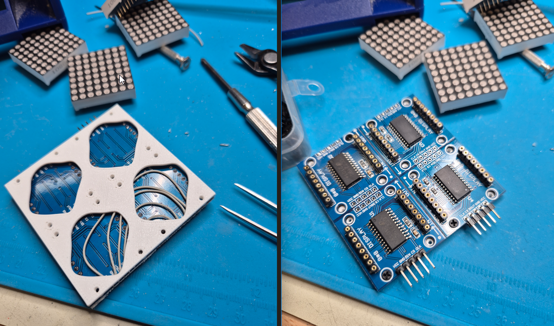
To get this all sorted out: Each side (one panel) of the cube has four modules directly connected and the cube is build of 6 such sides.
I define two struct for the coordinates:
struct CubeCoordinates
{
  uint8_t panel; // side of the cube 0..5
  uint8_t x; // x coordinate on panel 0..15
  uint8_t y; // y coordinate on panel 0..15
};

struct ModuleCoordinates
{
  uint8_t addr; // address of module 0..23
  uint8_t row;  // row on module 0..7
  uint8_t column; // column on module 0..7
};
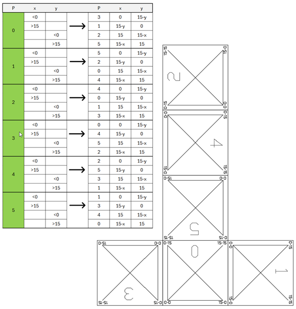
The origin (x=0|y=0) of each side (panel) is on the lower left. The modules are placed and rotated as shown below, (offset is panelNumber * 4):
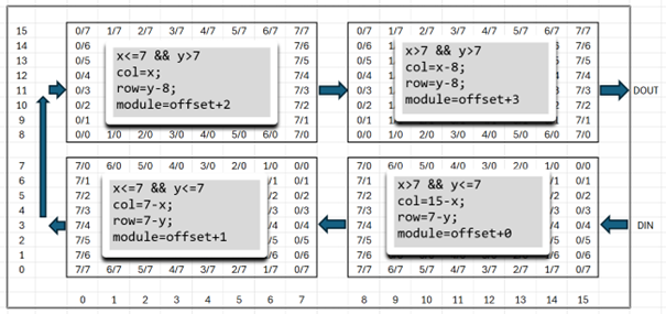
This way I can convert from CubeCoordinates to ModuleCoordinates (the other way is not needed).
ModuleCoordinates Cube2Module(CubeCoordinates c)
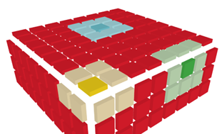
Next problem is finding the neighbours at the edges and corners, where the adjacent cell is on another panel. That depends on how the panels are aligned to each other. To solve this, I waited until the whole cube was built. By displaying a test pattern, I could easily write down the panel number and orientation of each panel to build the big if/then/else countNeighbours function
uint8_t countNeighbours(CubeCoordinates c)
With this Pattern the orientation of each panel can be seen and the coordinate transformation, if a neighbour is outside of the panel, can be determined.
Software
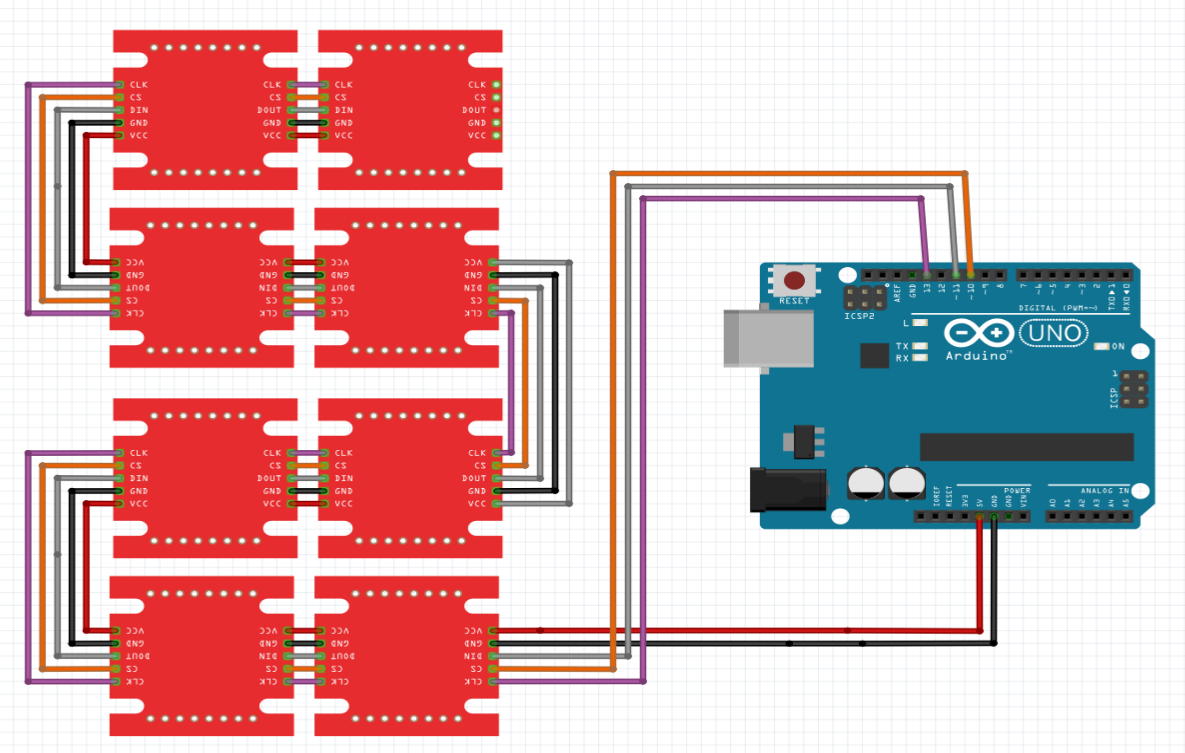
To test, if my idea would work, I used ready-made MAX7219 modules with LED...
Read more »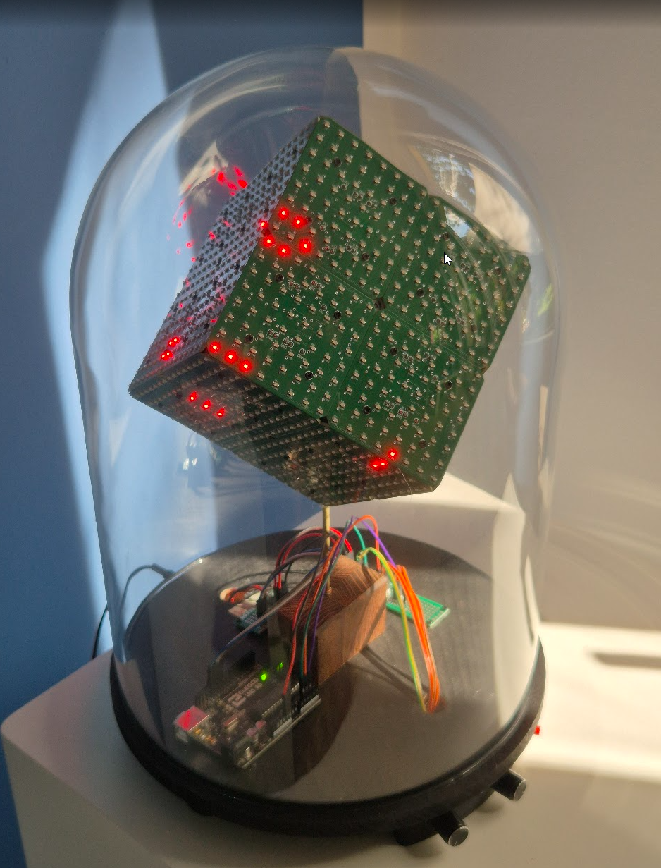


 But for Conway's Game of Life, the neighbours have to be counted. And the neighbour could be on another side. But that has to be done in another step, as this involves how the cube ia actually build and how the sides are connected to each other. For now each side is on its own.