 Bud Bennett
I've finally settled on the topology (and PCB layout) below. It is amazing how many different buck regulator ICs can be used on a fixed PCB layout.
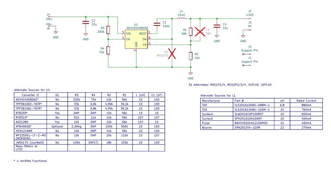
I follow a few simple steps to select components for this design topology:
- Pick a suitable IC based upon performance/cost tradeoff.
- Pick a range of possible inductors that will be compatible with the chosen IC
- Set the desired output voltage with R1 and R2.
- Check the datasheet input/output capacitor requirements for value and voltage rating.
- Set the value/voltage of C1 from the datasheet.
Sorry about the few choices for the diode. It was in my inventory so I went with it.
Pick IC:
I use Digikey and LCSC (JLCPCB) almost exclusively. Inputting search parameters at both of these websites is more art than science.
At LCSC, use basic parameters to sweep in as many parts as possible. If you set too many restrictions you will get very few candidates. Here is what seems to work (for me) at LCSC:
For category DC-DC Converters: Function=buck, output type=adjustable, Frequency= 1.2-2.1MHz. You can also select synchronous switching if desired. Then select the package types one at a time, SOT23-6, SOT26, TSOT23-6, etc. (If you check them all at once you won't get very many results.) Now you can manually eliminate certain parts that won't tolerate higher voltages > 20V, and by price and availability. For the rest you can click on the datasheet and view the pinout to see if it is compatible. After that run through the feature list and check the efficiency. It's rather tedious. Alternatively, you can just input one of my part numbers into the search bar and see what pops up.
At Digikey, get to the category "Voltage Regulators -- DC DC switching regulators" and select Stocking Options=In Stock, Product Status=Active, Packaging=Cut Tape, Topology=Buck, Output Type = Adjustable, Package/Case=SOT23-6+SOT23-6thin+TSOT23-6. Then select the frequency range -- I use 1.2-2.25MHz. Plug in the quantity you wish to buy to eliminate the minimum quantity candidates. When I did this it produced 91 candidates in order of increasing price. Many of the candidates will not have the input voltage range you need but you can sort them out visually. Finally, check each datasheet for the matching pinout to the layout and proceed to review feature set and efficiency. Alternatively, you can just input the part number you want and get right to the page for it.
The candidate list I created does not pick favorites, but I do have my preferences. Prices start at less than $0.15 for a non-synchronous switcher. I prefer a synchronous switcher -- it's slightly more expensive, but also a bit more efficient and eliminates the cost of the free-wheeling Schottky diode. I went for a lower output current: 500-600mA instead of 1-2A. The current load is pretty modest at 50-60mA, so a smaller set of internal switches will probably yield a better efficiency at lower load currents because the switch transistor gate capacitance will be smaller. I also prefer the higher 2MHz switching frequencies to keep the output ripple current within limits while using a smaller inductor value. It's difficult to justify at 500mA ripple current with a load of only 60mA.
I put question marks in columns where I could not determine the best component value to match the IC. Some data sheets provide a range of inductor values (or even suggested part numbers). Others simply indicate a maximum inductor value for a specific output voltage. And others provide a vague suggestion about larger inductors being better for lower current loads. Having designed these types of switching converters in a previous life, I have thoughts about that. There is a comparator that senses the inductor current and decides when to turn off the switch. If the ripple current is too low, because the inductor value is too large, the comparator might not be able to make the proper decision and a problem ensues.
Just because there is an equation for ripple current doesn't mean that the converter will make it happen. If there is significant delay in the current comparator then the inductor current peak will be larger than intended and the ripple current will be larger. The only way to check for this is via simulation or an inspection of the typical waveforms provided in the datasheet...or when you test it on the bench.
Pick Inductor:
The main constraint is package size -- 0806 (2016 metric). Height doesn't matter much since most inductors of this size will be thinner than 1.2mm. The footprint on the PCB will probably fit all the available candidates. Select a shielded inductor to reduce EMI.
The buck converter datasheet will give a recommendation that inductor ripple current be about 30-40% of the max load current, which is ridiculously small in our case and would call for a very large (>100uH) inductor; or the datasheet will specify ripple current be 30-40% of the max switch current which will work but make the ripple current unreasonably large.
The peak inductor current is given by this equation:
Which yields curves like this for Vout = 5.3V:
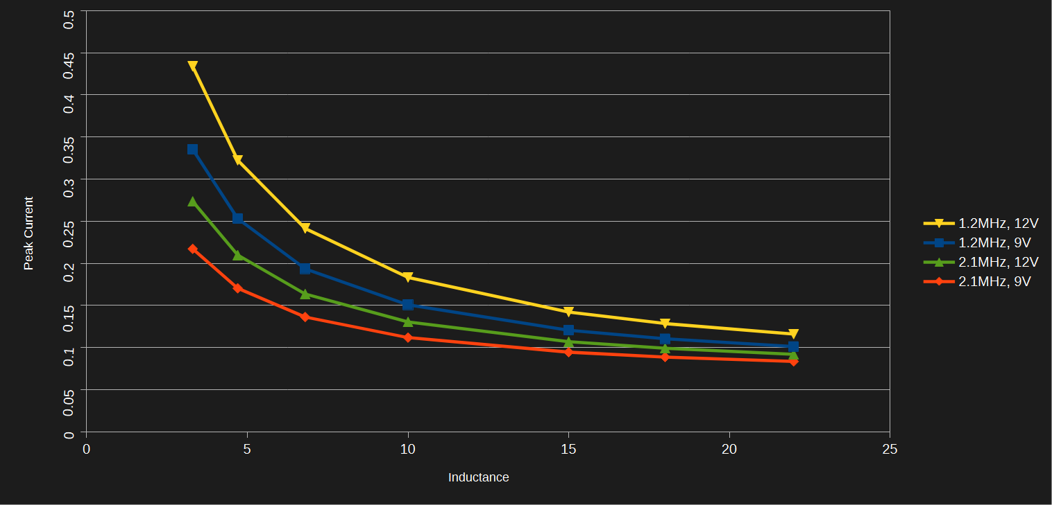
Remember to account for the tolerance of the inductor, usually +/- 20%. Avoid small inductors for two reasons -- the larger peak currents will require a larger switch current rating and also cause higher power dissipation in the switches (or switch+diode), input/output capacitors and inductor. You should avoid large inductor values because they will saturate at lower currents and have larger parasitic series resistance which causes power loss. For me, the sweet spot is an inductor value between 10uH and 22uH. The 10uH inductor is a more common value and has better availability. I will also set the USB-C trigger board to output 9VDC.
So now I'm selecting a 2MHz converter and a 10uH shielded inductor with a saturation current above 200mA. The RMS current will be equal to ILoad + Iripple/( 2 * sqrt(3)) = 89mA. The inductor should have a heating related current significantly above this. It's not difficult to find an inductor to meet these specs.
Discussions
Become a Hackaday.io Member
Create an account to leave a comment. Already have an account? Log In.