 Mark Makies
Roverling’s first level of navigation control uses a magnetometer. It’s initially calibrated offline using all three axes (for spherical remapping), and then recalibrated on Roverling itself with a figure-of-eight manoeuvre to correct for hard and soft iron effects.
However, the magnetometer is only accurate when the device is level. That becomes a problem when Roverling drives up, down, or across slopes. To compensate, tilt correction is applied using pitch and roll, which are calculated from a three-axis accelerometer.
Unfortunately, this solution is limited: the accelerometer provides reliable pitch and roll data only when stationary. On rough terrain, movement-induced spikes render the data unreliable.
The next level of control comes from GPS. While useful, it has its own limitations:
- Updates are only available once per second.
- Reported precision is ~18 cm.
- Real-world accuracy (after acquiring ~20 satellites and allowing 15 minutes to stabilise) is closer to 50 cm.
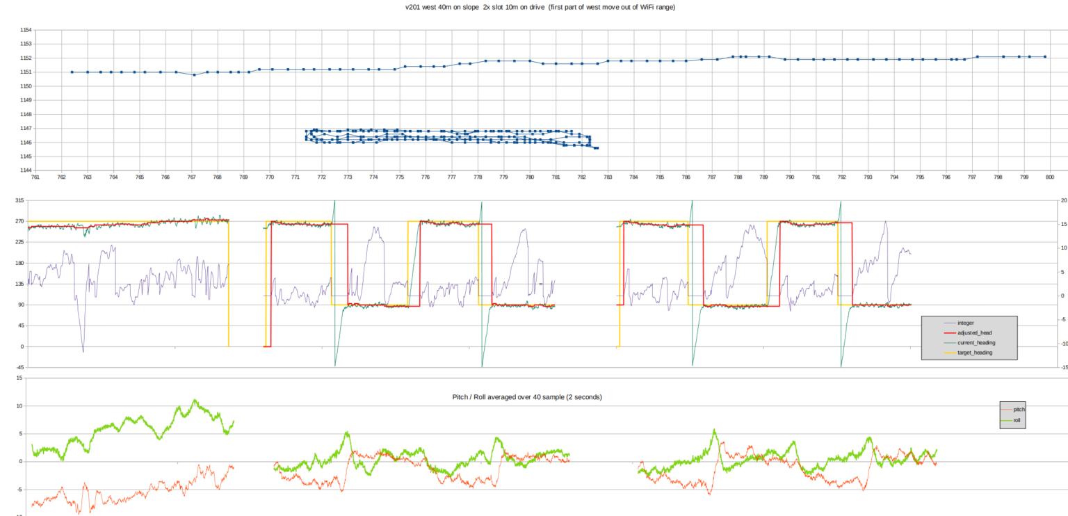
The first chart below (1 m/div) shows Roverling’s position during a fully autonomous (very slow) run:
- A 40 m straight line across a 10° slope: Roverling stays within a 1 m corridor.
- A series of tight 10 m slots on flat ground: again, deviations remain under 1 m.
That’s probably accurate enough to return to a previously detected object (e.g., a buried treasure).
The second chart tracks internal PID parameters as the vehicle drives back and forth.
So far, so good. For the next test, I suspended a string line overhead to check drift. Roverling ran autonomously using only the magnetometer for navigation. Still good.
To test the complete system in a real-world scenario, I ran Roverling on a sloping, slightly rough paddock - typical of our bush block. This was a fully autonomous run, executing a predefined grid search pattern.
To support this, I developed:
-
a command-line utility to generate a rectangular search pattern in Roverling’s PlayList format (used directly by the vehicle),
-
a simulator to preview the planned route and detect any logic errors before deploying,
-
a visual overlay tool that displays both the planned simulation path and real-time telemetry - useful for live monitoring and post-run analysis.
Once everything was configured, I loaded the playlist, positioned Roverling at the start point, and let it go.

I was hoping for so much more. This test was conducted across a slope, which affected both GPS and compass data. The next chart shows the same path as before. The heading arrows are derived from the magnetometer.
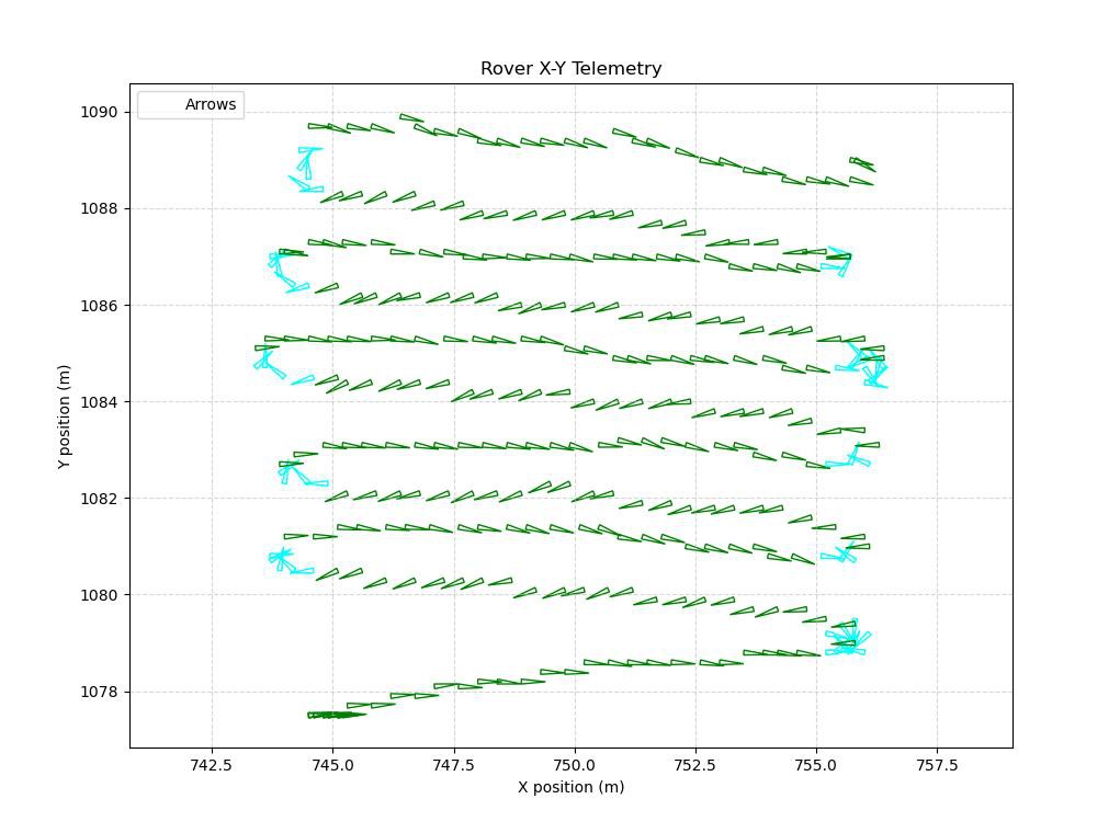 Observations:
- Compass heading is not entirely trustworthy when operating on bumpy ground despite pitch/roll compensation.
- GPS position drifts.
- Wheel encoders can’t be used either - too much slipping for reliable dead reckoning.
Solution:
Enter the Madgwick Filter: a lightweight, efficient sensor fusion algorithm that can run in real-time on an RP2040. I implemented it in Python to combine data from:
- Gyroscope (short-term orientation stability)
- Accelerometer (gravity direction)
- Magnetometer (absolute heading)
to estimate orientation (pitch, roll, yaw [aka heading]) in full 3D.
It was not easy to code - but it works brilliantly.
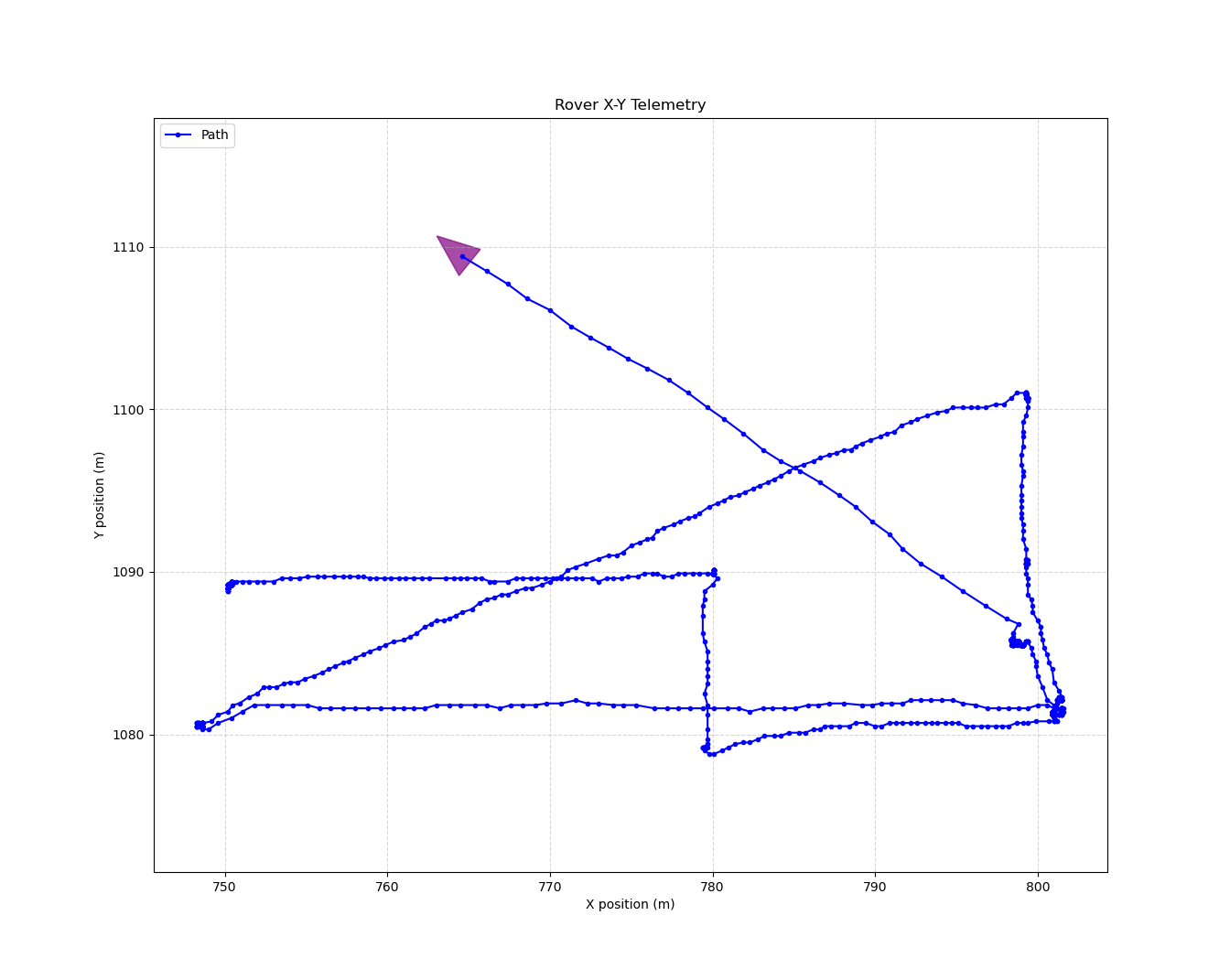
The final chart shows Roverling executing a straight-line autonomous path using the Madgwick-derived heading. Early signs are very promising.
Now, once the weather fines up, back to testing
Discussions
Become a Hackaday.io Member
Create an account to leave a comment. Already have an account? Log In.