 Jorisclayton
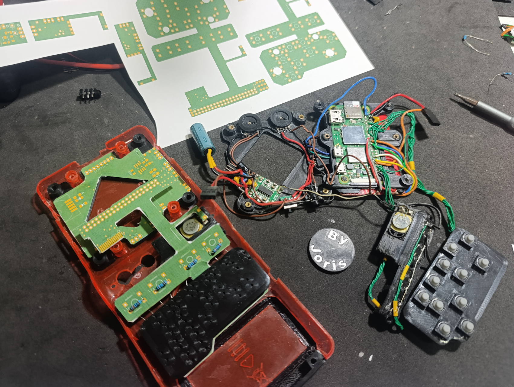
I have completed the schematic and layout of the three printed circuit boards (PCBs) for the project, and I am ready to proceed with their production. Before finalizing the design, I conducted a series of tests to ensure that the boards would actually fit inside the console. To do this, I printed the layouts on paper and cut them out to test how they would physically fit. This gave me the opportunity to modify the shape of the boards slightly to ensure they would fit perfectly in the available space inside the console.
The three boards have the following functions and features:
-
Main Board: This board will be responsible for several controls, including:
-
Volume control.
-
Audio generation using PWM (pulse-width modulation).
-
Display brightness control using a PWM circuit with an NE555 timer.
-
Headphone jack.
-
Mute switch for audio.
-
Switch to disable controller inputs (to allow the console to be stored in a pocket without unwanted inputs being triggered).
-
Expansion for additional connectors.
-
-
Power Board: This board will manage the console’s power and energy control. Its functions include:
-
Receiving power from the battery and the charger.
-
Regulating the voltage to 4.5 volts for the Raspberry Pi Zero.
-
Monitoring the battery level, using a TL431 to alert the user when the battery is nearly empty.
-
Power switch to control the enable pin of a step-down converter (97% efficiency tested with a bench load).
-
-
Flexible Board: This board will be responsible for connecting everything. Its functions include:
-
Connecting the controller buttons, speaker, USB pins, TV Out pins, and the TFT display to the Raspberry Pi’s GPIO pins.
-
Connecting the Main board to the Raspberry Pi by a 14 lines flexible connector.
-
Avoid the use of many wires, mostly from the controller buttons.
-
The expansion connector on the main board will include the USB data pins and the RCA output from the Raspberry Pi. This will allow for the connection of USB controllers or keyboards, USB flash drives, and other devices. Additionally, it will be possible to directly connect the console to a TV using the RCA output. These additions provide greater versatility and functionality to the console, expanding the options for interaction and connectivity.
These boards are a significant step toward completing the project, and I have already run several tests to ensure they function correctly before final production.
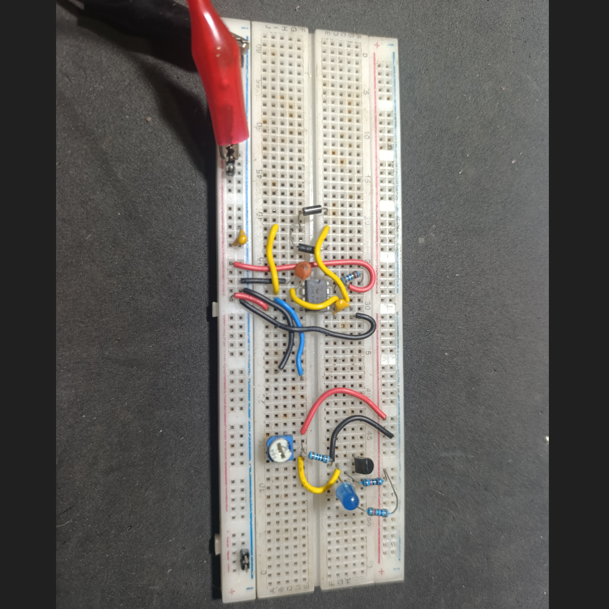
I also built some circuits on a breadboard to test the PWM generator with the 555 and the battery monitor with the TL431, and both worked well before I transferred them to the PCBs. The PWM brightness control will be adjusted with a rotary potentiometer, similar to the one used for the volume knob. The TL431 only needed a few resistors to work properly, but I also had to create a voltage divider on its output to adapt the levels. The TL431 was outputting 2V for "off" and 4.5V for "on," so I adjusted it to 1V for "off" and 2.5V for "on," making the signals compatible with the Raspberry Pi’s GPIO pins.
I’m attaching some photos showing the console with the new 3D-printed parts, along with the paper PCBs I made to test the fits and footprints. These images give a good look at how everything lines up and fits together before moving on to the final PCB production.

Discussions
Become a Hackaday.io Member
Create an account to leave a comment. Already have an account? Log In.