There were two main approaches I could take:
Option 1: Hijack the Capacitive Buttons
This involves adding electronics that take over the touch buttons. Since the device behaves autonomously (e.g., it automatically switches off after sitting at power level 0 for a while), I’d also need to read all the LEDs—including the 7-segment display—to monitor its current state and react accordingly.
Pros:
-
Straightforward—no need to reverse-engineer the communication protocol
-
Built-in safety features remain fully active
-
The display still shows the current power level
Cons:
-
Requires careful tuning to reliably trigger the touch sensors
Option 2: Intercept the Communication Between Control and Power Boards
This means placing a microcontroller between the control PCB and the power PCB. It can pass through normal communication during manual use, and take over when automated PWM control is needed.
Pros:
-
Offers more direct and flexible control
-
Potential for finer-grained control beyond the default 0–9 power levels
Cons:
-
Requires reverse-engineering the communication protocol
-
Need to fully understand the built-in protection mechanisms
At the time, Option 2 seemed the most promising—or at least, the most fun from an electronics perspective—so I went with that.
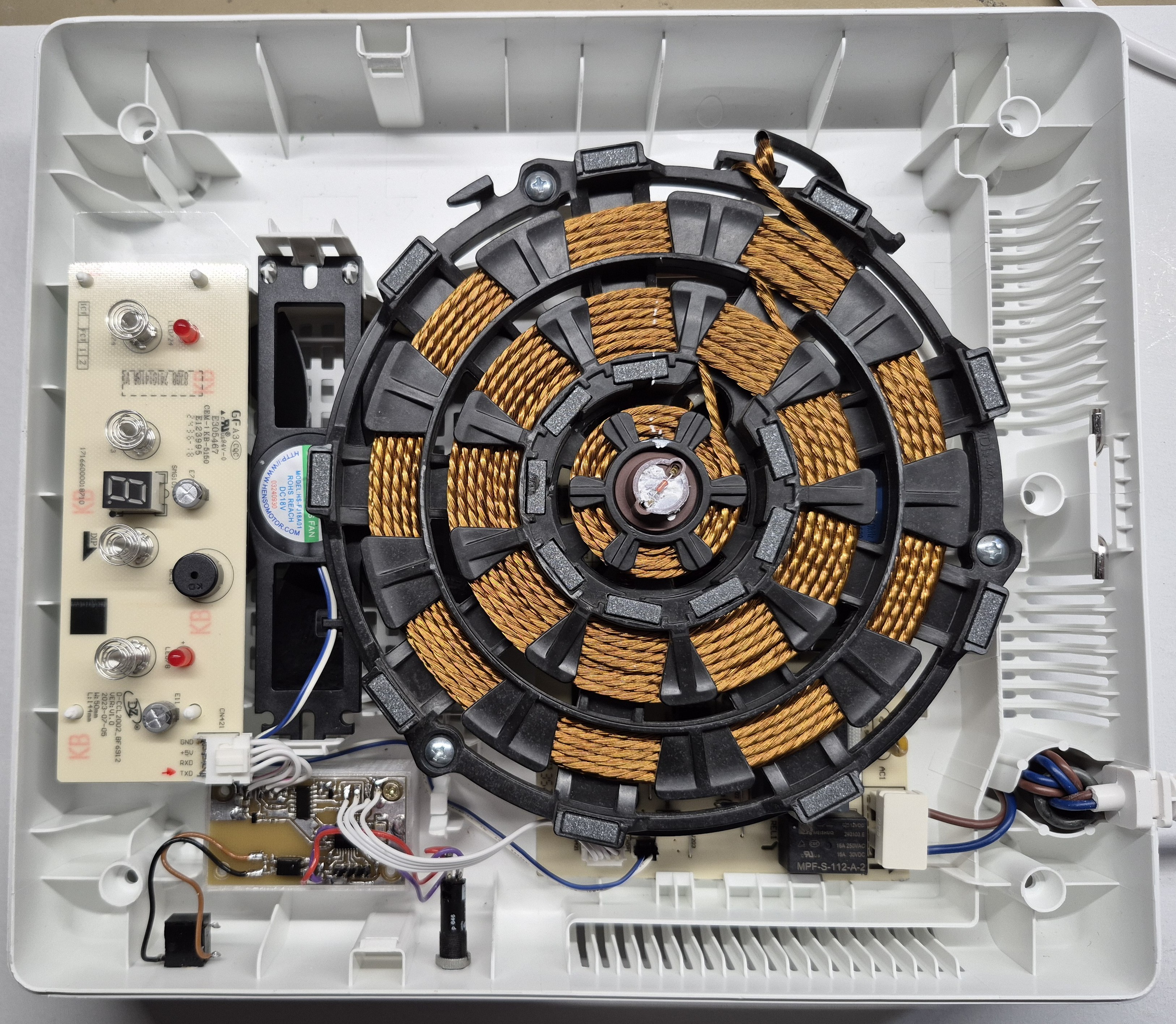
Here’s a photo of the final working setup. More details to follow!
Discussions
Become a Hackaday.io Member
Create an account to leave a comment. Already have an account? Log In.