Using an isolated oscilloscope, it became clear there's a master/slave serial communication setup between the front panel (master) and the power PCB (slave).
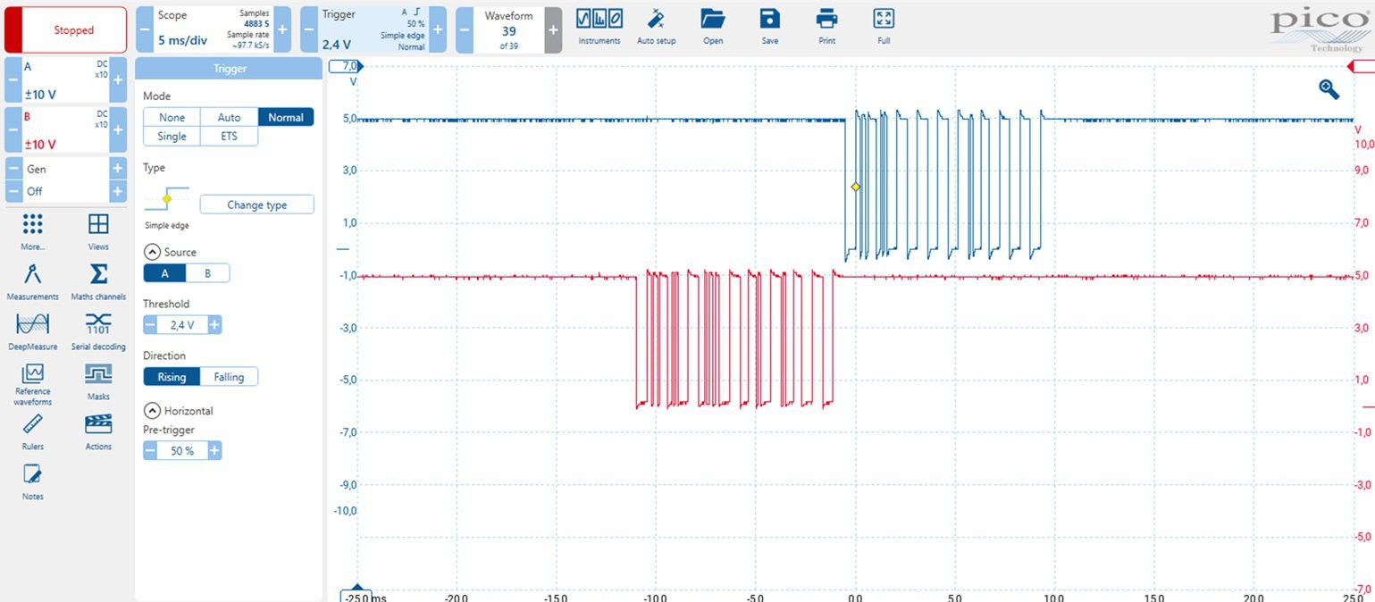
The communication uses standard 9600 baud, 8 data bits, no parity, 1 stop bit, and LSB-first format.
-
The front panel transmits a 10-byte message every 100 ms.
-
The power PCB responds with a message of equal length.
You might wonder why such a simple application needs this much data. The answer is probably a mix of redundancy/error correction, and the fact that modern designers don’t worry too much about a few extra bytes.
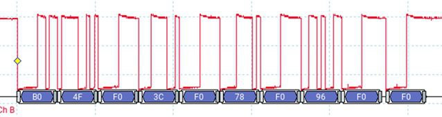
Analysis: Front Panel → Power PCB (Red Trace)
Here’s an example of the message when the power level is set to 0.
These are the telegrams corresponding to each possible front panel state (with byte 0 sent first).
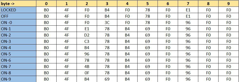
I initially tried asking GPT-4 to decode the structure, but that didn’t lead anywhere useful. So, I went old school: pencil and paper. The result?
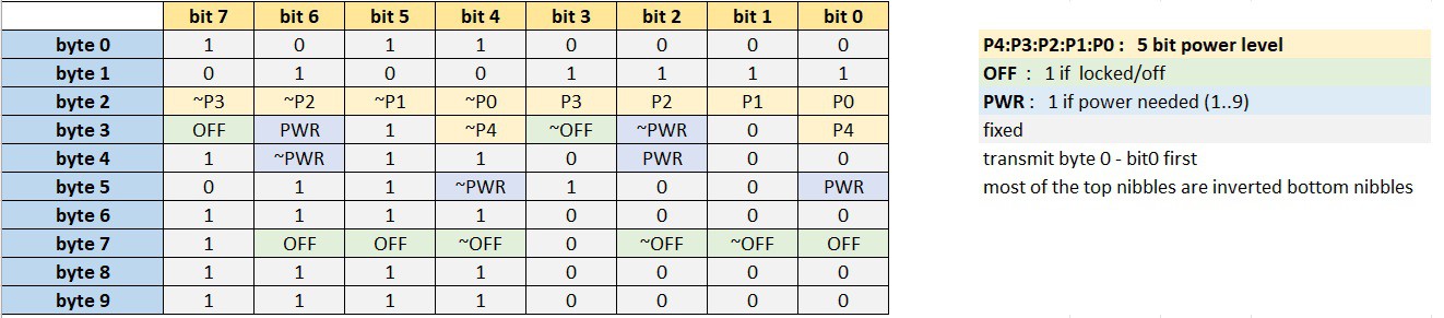
A lot of fixed values and redundancy, just as expected. For example: some values are inverted (~) as basic checksums.
There are 5 bits used to encode the power level, allowing for up to 32 distinct values. This means the system is technically capable of finer power control than what the front panel offers, which only allows selection of levels 0 through 9.
However, there are two important limitations:
-
The lowest power level available via the protocol still corresponds to front panel level 1, so there's no way to achieve a power output lower than that baseline.
-
Interestingly, front panel level 9 corresponds to a power level value of 20 (decimal) in the protocol, indicating that only a portion of the available range is used.
Analysis: Power PCB → Front Panel
This direction was a bit trickier. Some of the values changed with every transmission.
Below is a capture of 15 sequential messages ( OFF state).

After a beer and some focused thinking, here's what I figured out:
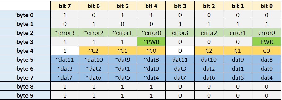
-
The 4 error bits appear to encode error conditions.
-
For example, error1 seems to indicate “no pot detected” on the cooktop.
-
I didn’t dig much deeper, since the PWR bit turned out to be a reliable indicator of whether power is being delivered or not.
-
Parameter Cycling Logic
One part of the message changes continuously: every transmission includes one of five different data parameters. This is controlled by 3 bits C2:C1:C0, which cycle through: 0 → 1 → 2 → 3 → 4 → 0 → ...
Each parameter is sent as a 12-bit value dat11:dat0
Reverse-Engineering the 5 Data Parameters
After some experimentation, here’s my best guess at what each parameter represents:
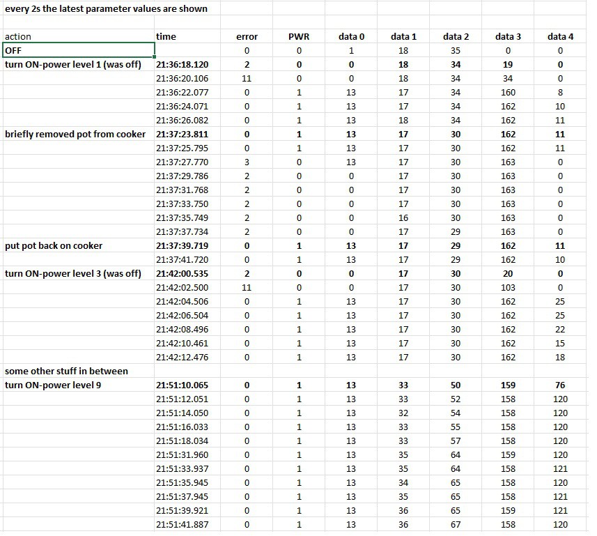
Parameter Likely Meaning
Data 0 : Unknown
Data 1 : Temperature of something
Data 2 : Temperature of something else
Data 3 : Voltage indication ? (drops slightly as power increases)
Data 4 : Power indication
However, my interface doesn’t depend on these values. It simply checks that the PWR bit is in the expected state (i.e., ON when power is requested).
It’s worth noting that the power PCB has solid self-protection features. For example, it automatically drives the cooling fan when necessary—independent of external control.
Discussions
Become a Hackaday.io Member
Create an account to leave a comment. Already have an account? Log In.