 Tim S
Tim SMy Streamdeck recently died on me, leaving me without a convenient way to toggle the lights/fan in my office (among other things). Instead of buying a replacement, I decided to try and built one myself, without the button displays, but with another feature I think I'll end up preferring in the long run.
A year or two ago I picked up a new curved, ultrawide monitor, and discovered when I got home that my monitor arm was not up to the task of keeping it vertical. It could keep it off the desk, but it would droop and slowly lean forward. Instead of buying a stronger monitor arm, I opted to design and print a set of modular organizers that fit underneath the monitor and help support the weight. I wanted my new control pad to be built inside one of these modules.
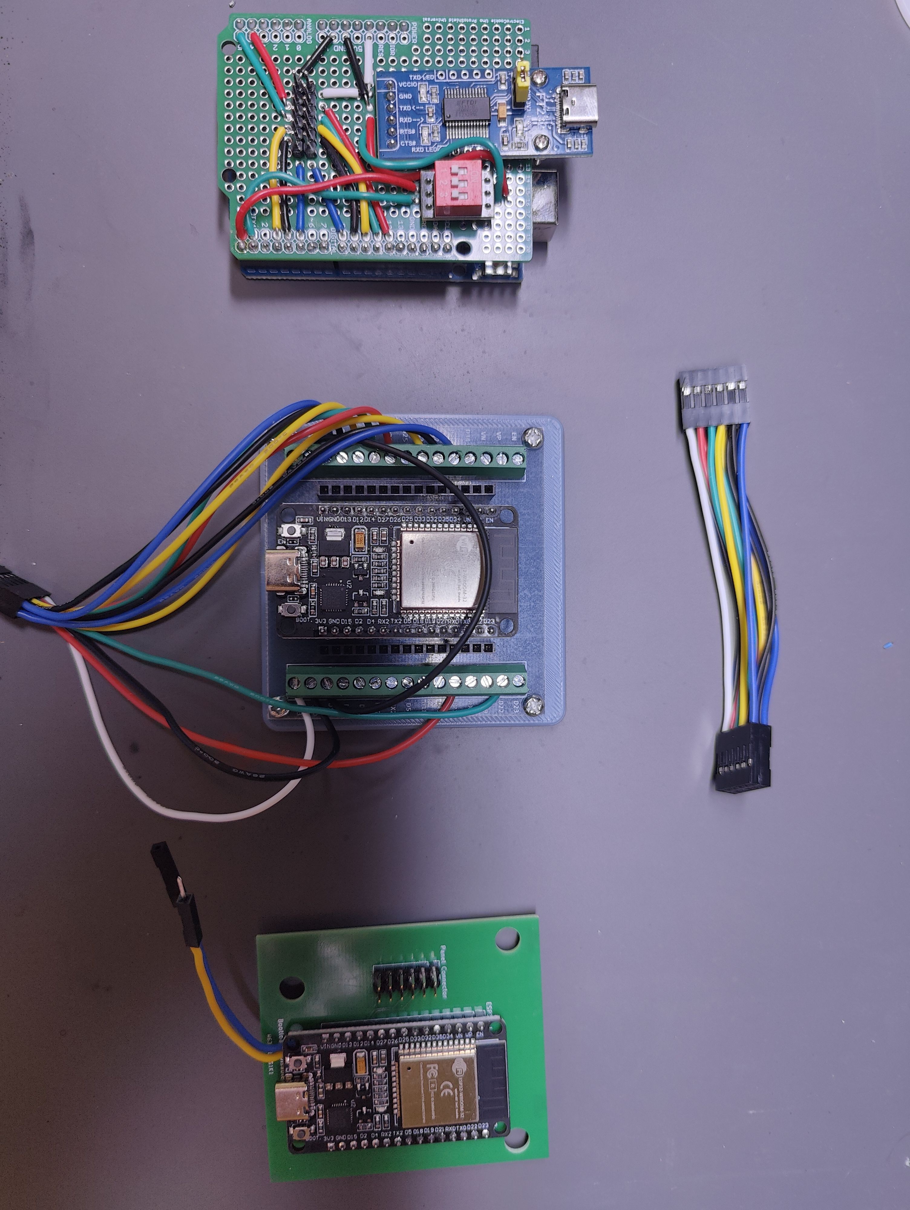
For the electronics I started with an Arduino Uno. After some breadboard prototyping of the individual components, I switched to a protoboard shield which I could add and remove from the Uno. Fairly happy I went this route, as the Uno didn't end up working out, and this means I don't have to desolder it from a normal protoboard or something to get it back out to use for something else.
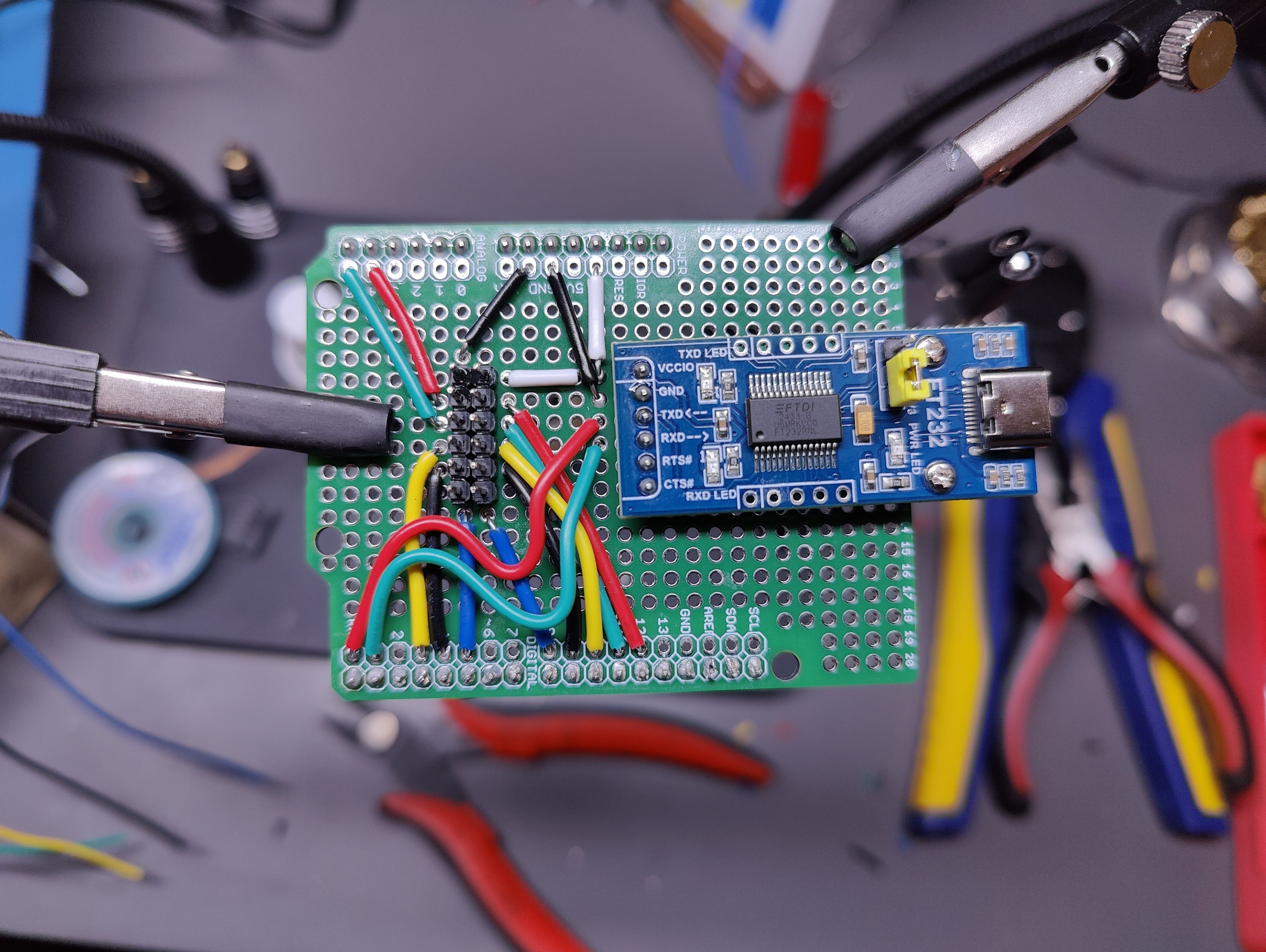
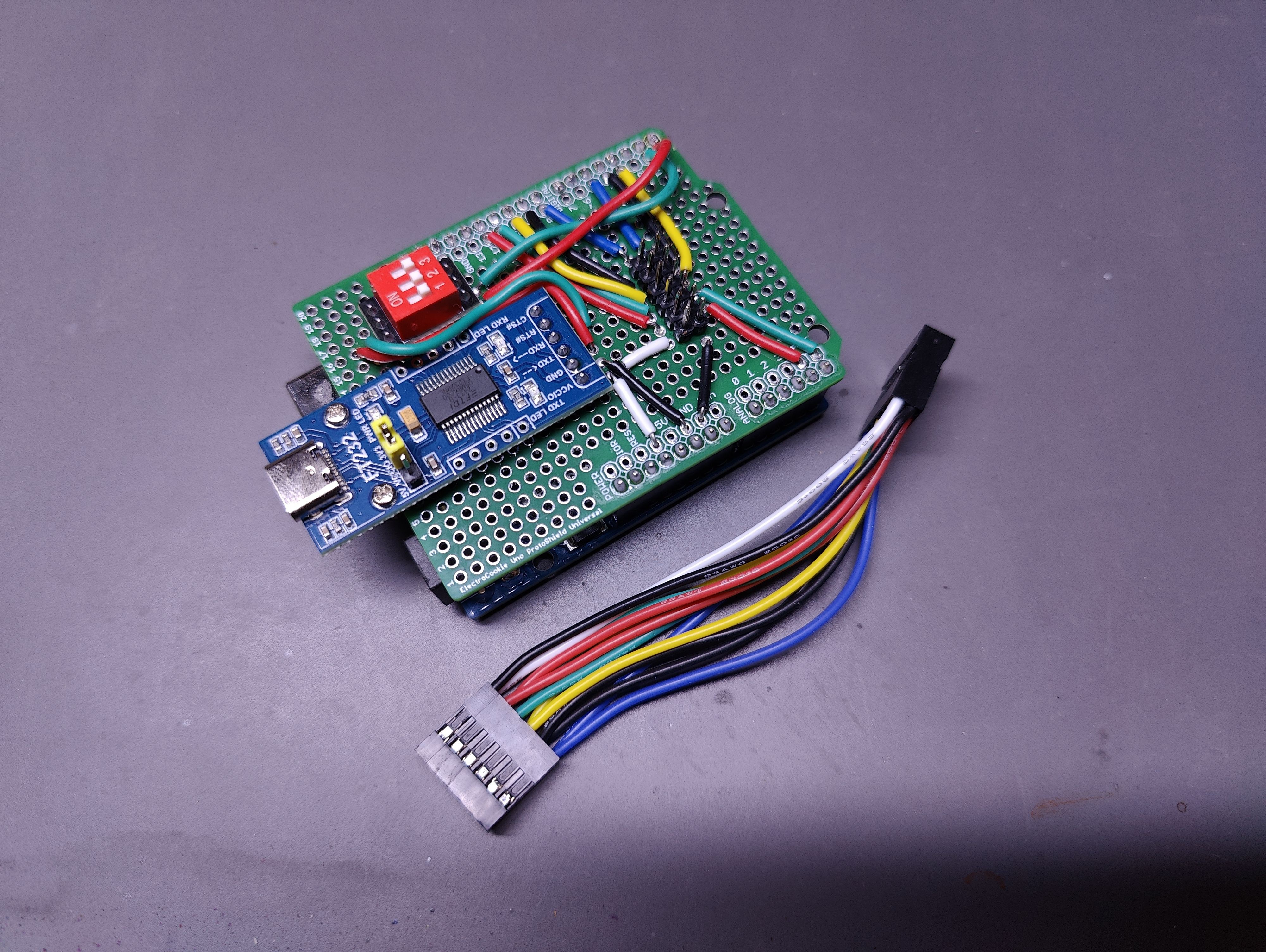
At this point I hit the first potential snag with the Uno. Since I wanted the device to communicate with the PC over serial I had attached a a USB-to-UART to the protoboard. Unfortunately, I didn't realize at the time that connecting it to the TX/RX pins would disable programming the Uno, so every time I wanted to deploy new code I had to remove the shield from the Uno, which was rapidly wearing on the pins, and just about pulled the headers off the Uno. To resolve this I modified the protoboard so that I could put a dip switch between the Uno and the USB-to-UART. I only had a 3-switch on hand, so one of them just didn't get wired up. But at least now I could disconnect it temporarily to program the Uno.
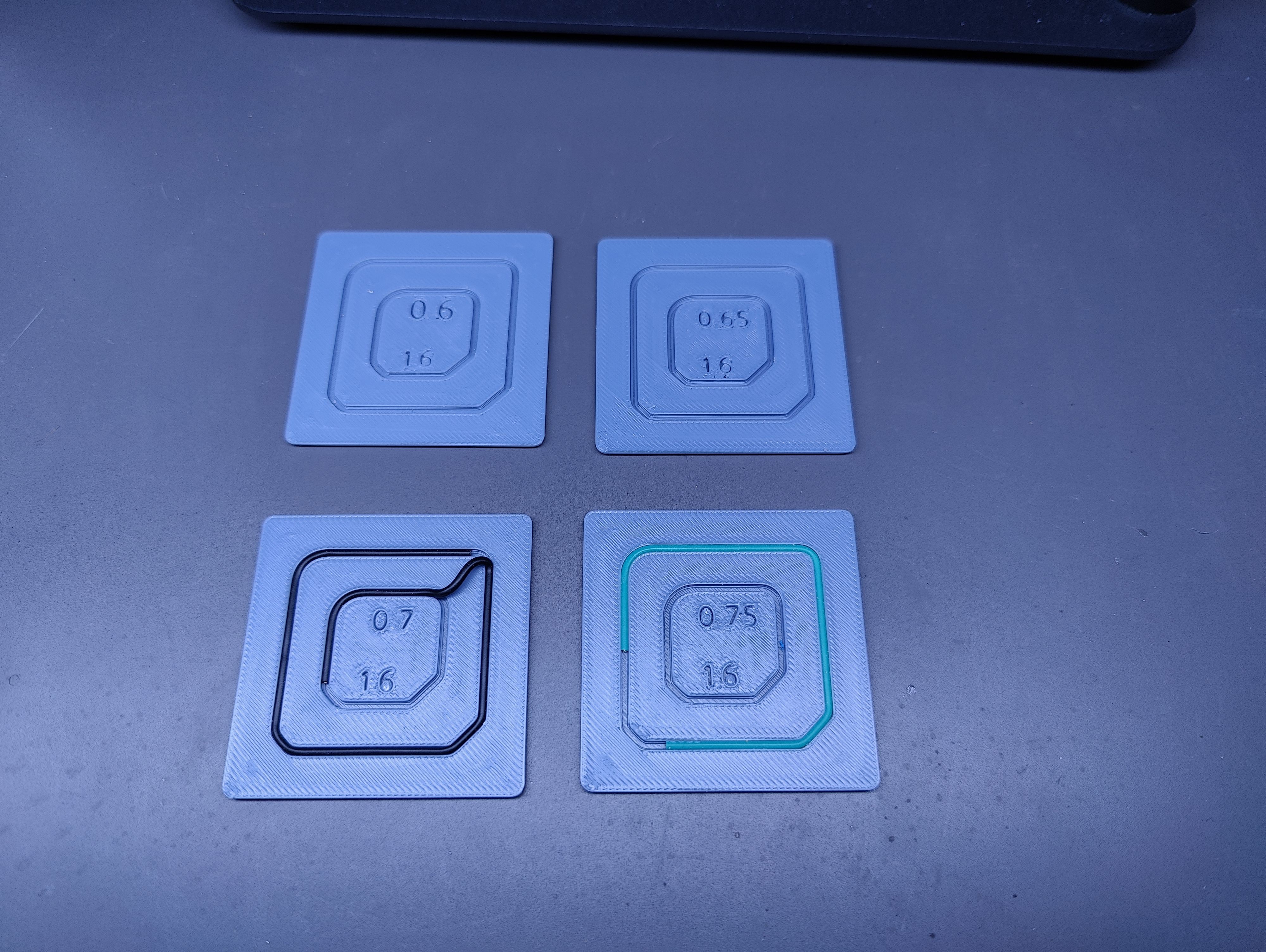
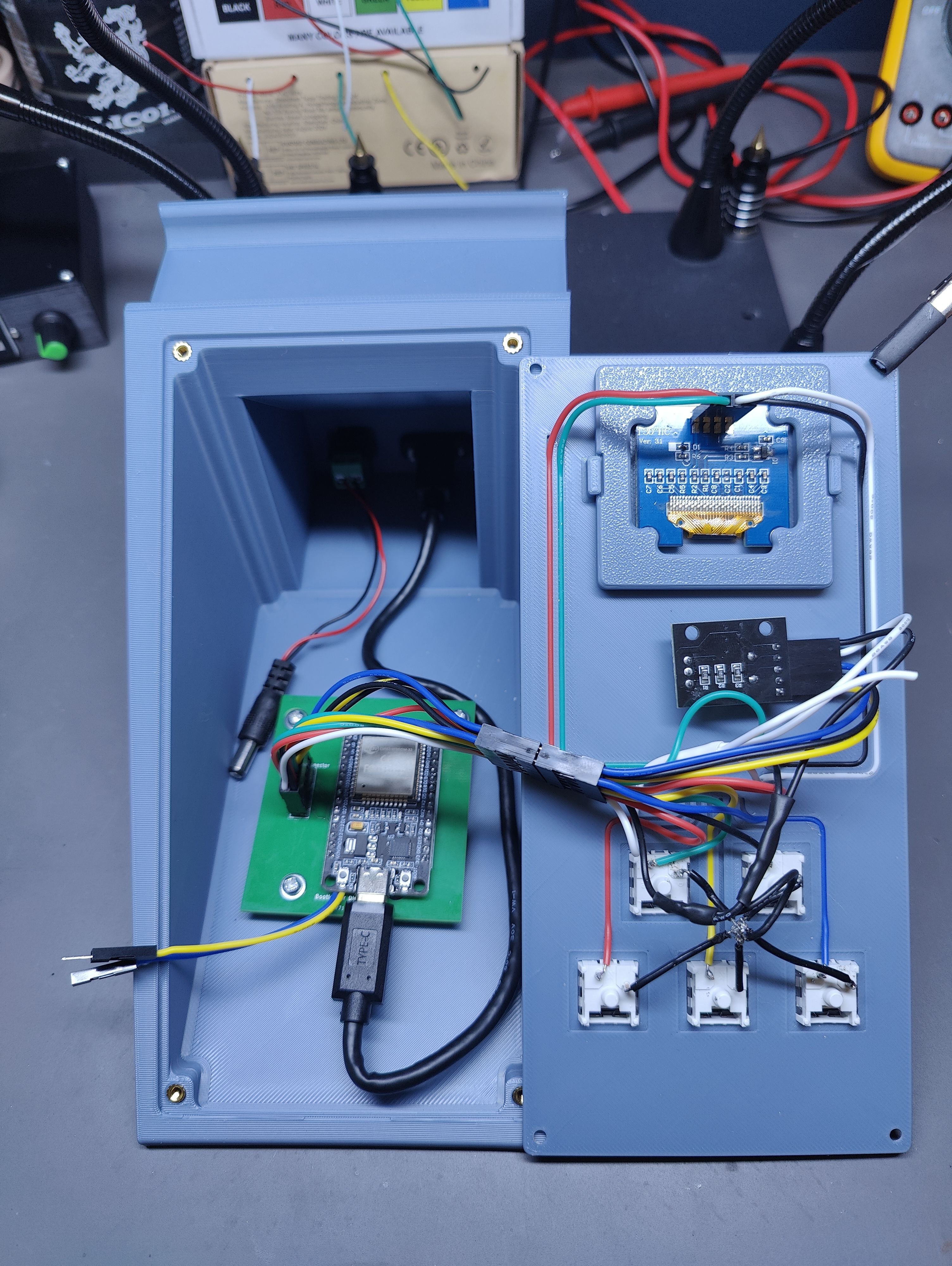
In parallel with this I was working on the 3D printed enclosure. I designed it in two parts - the main body with the general shape, the monitor support, and holes for running cables through the back, and a (mostly) flat control panel.I thought it would be interesting to see if I could route the cables embedded in the back of the panel, so I did a few test prints to experiment with it before dialing in an embed depth for the wires I wanted to use.
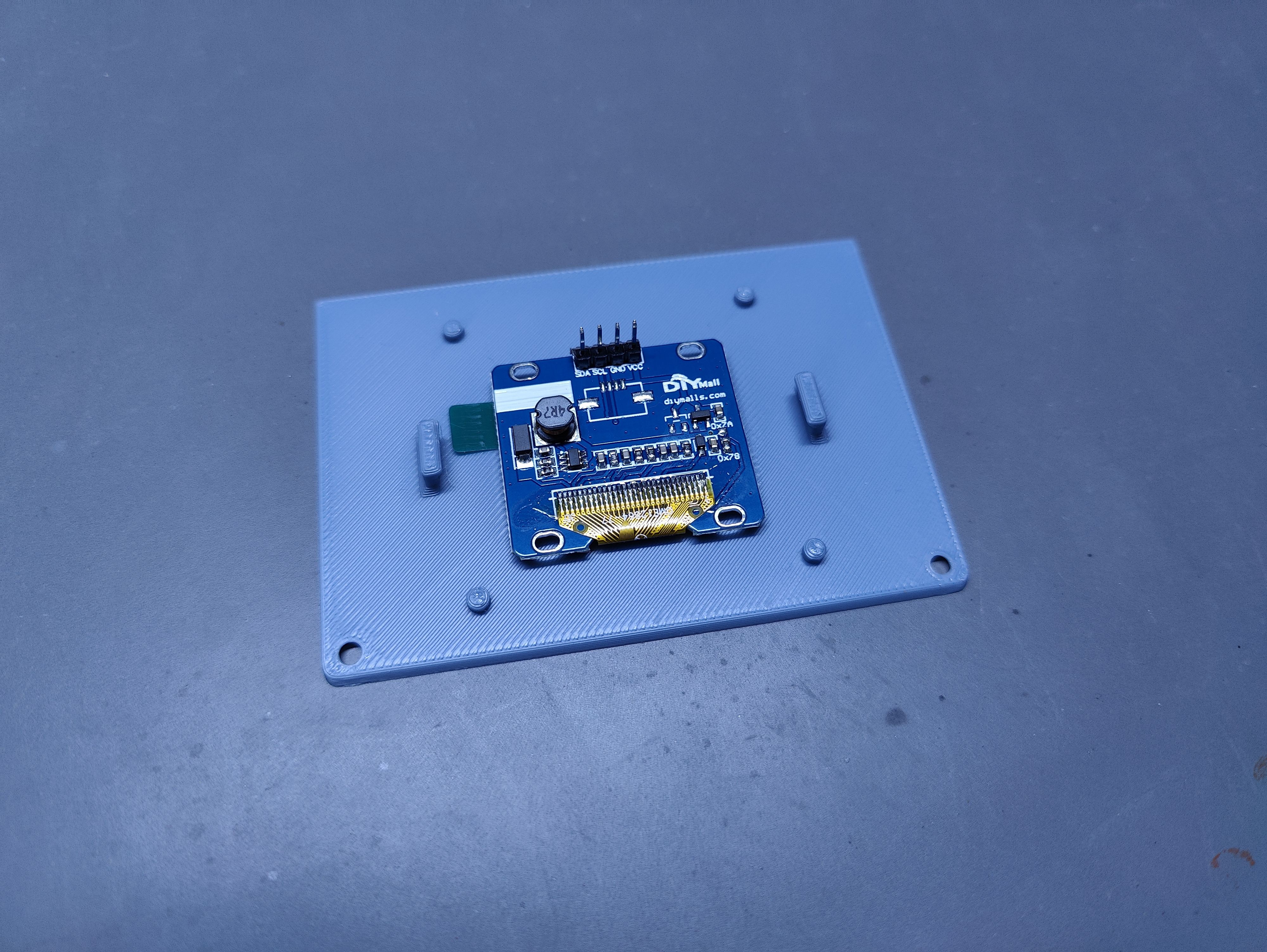
With that figured out I also had to figure out a way to attach the display to the panel, since the panel would be far too thin for heatset inserts, and I didn't want more bolt heads sticking out the front of the panel than necessary. I went with a press-fit clip that fits over the back of the screen:
After that it was mostly a matter of soldering on a bunch of wires to wrap up the panel:
You may have noticed another interesting difference there; that's not an Arduino. This is actually the third iteration. At one point I ran into the memory limits of the Arduino trying to implement a nested menu for the screen and switched to an ESP32. I started with a breakout board and some screw headers and ran with that until I was fairly confident in the design. This was mounted in the enclosure using a simple adapter plate I printed to switch from the breakout board mounting holes to the ones on an Uno.
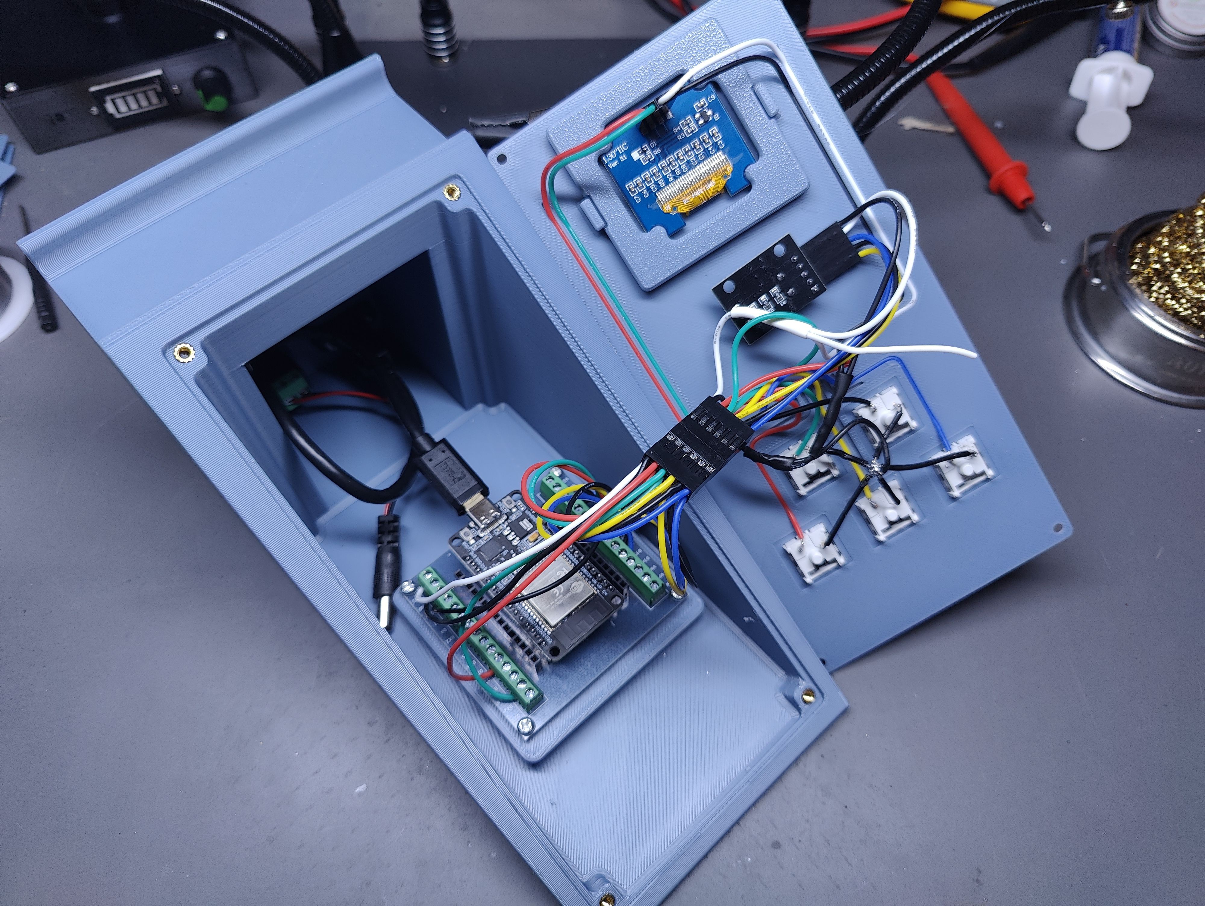
Then I put together a dirt-simple PCB in KiCad and sent it off to PCBWay to have a handful manufactured. It's basically just a breakout board for the handful of pins I need, but there's also a pair of wires coming off it that can be connected to disable pushing new code to the ESP32 (mostly to keep me from accidentally breaking it when deploying to other ESP32s in the future).
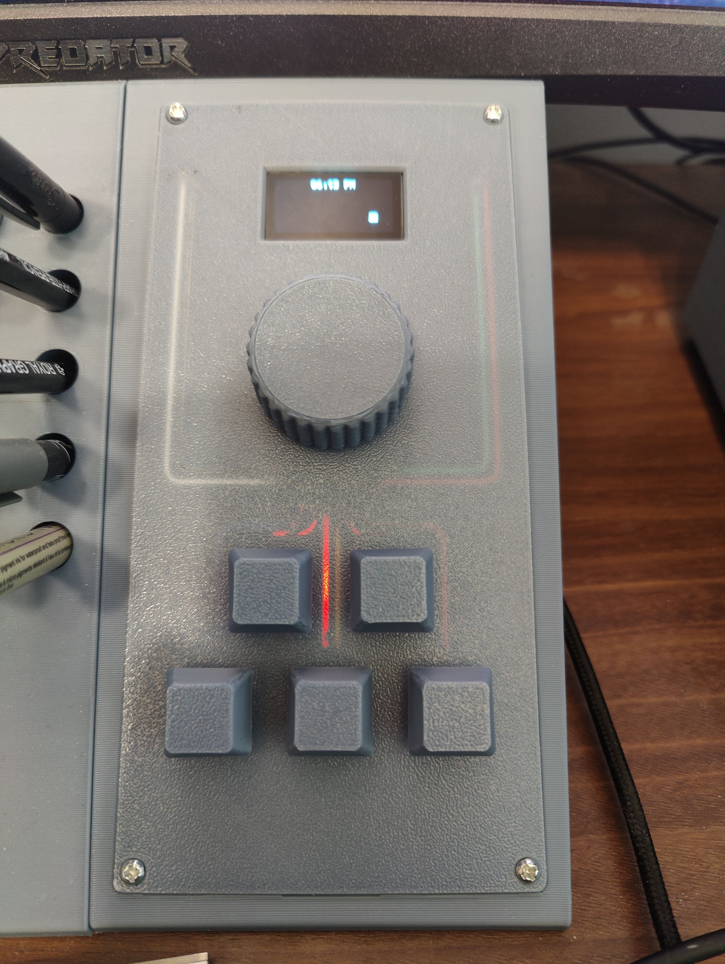
With the panel in place and some custom key-caps and a knob printed in the same material, I called it V1 and have been using it for a few days.
From a software perspective, the code on the ESP32 waits for key presses and sends signals to the PC via the serial connection when they're first pressed. The potentiometer does not directly send signals to the computer. Instead, rotating and pressing the dial allows me to navigate a nested menu on the little screen. Selecting certain options sends serial signals to the PC. Currently none of those are triggering anything on the PC side, but I intend to use them to control future projects (including a On Air/Busy sign for the office door to let the family know when I'm in meetings)
There is a rust app running as a service on my PC, which basically listens for the serial signals, and simulates key-presses or sends requests to Home Assistant to manage smart devices. The device identifies the control panel by stepping through USB devices connected to the PC and sending each an "id" request via serial, and waits for one to respond with "desk-control-panel".
As far as potential improvements: running the wires embedded in the panel is cool, and I actually quite like how they're visible through the panel, but some of the paths were way too short to be useful. The knob I hope to reprint and improve on the transition from the top to the knurling to make it a bit smoother. Additionally, I may investigate a way to change how the USB device identifies itself to the PC, so Platform IO will stop trying to deploy other projects to it. That said, so far it's been working great, and I look forward to expanding on its capabilities in the future.