 Daniel
The vision
In the end, the flashlight should be bright and have a long battery life. You don't need a flashlight, which is dimmer than your smartphone light. And you sure don't want a flashlight which runs out of battery in the middle of the night. However, brightness and battery runtime rule each other out. I therefore decided to use a small switch to toggle between bright and very bright.
As I had a lot of Elfbars to upcycle, I wanted to keep the cost per Elfbar low (< 2€). The design should also be easy to manufacture, so I could turn around dozens of Elfbars (we'll see how that one turned out).
The hardware
To charge the LiPo, I reverse engineered the popular "TP4056" charging modules. They contain the charger TP4065, a battery monitoring IC (like a FM2113) and dual FET FS8205A. All chips together only costs some cents and offer many protection features. The only flaw is a missing power path feature: when the flashlight is charges while on, the battery may discharge or be charging indefinetly, depending on the charging current. I therefore implemented the popular PowerPath fix, using a MOSFET and a diode. To drive the LED, I utilized the CN5710 constant current driver. With a resistor, the LED current is programmed. An additional resistor can be switched in parallel, to change the brightness. This is done by a MOSFET, hooked up to the flashlight switch. To have a nice modular design, I used JST SH connectors to connect the battery and LED.
I decided to use a seperate PCB for the LED. The LED PCB is made from aluminum, to help dissipate excess heat. The wires are soldered directly to the LED, as the cutout in the Lens is very small.

The PCBs are held in the Elfbar with 3D-printed parts. These are press-fit, so no glue or screws are required. Additionally, I made use of a spacer, to separate the (possibly) hot LED PCB from the LiPo.
Manufacturing and assembly
I ordered the PCBs in panels, and assembled them by hand. The LED PCB were very simple, as there is only one part per PCB, and the solder pads are huge. The charger PCBs were quite challenging however, as they are double-sided. For the side with the most components, I used regular lead-free paste and a hotplate. The other side was assembled with low-temperature paste and a heatgun.

The batteries and LEDs were connected to the charger PCB using pre-crimped wires.
 Andrzej Strzała
 makeTVee
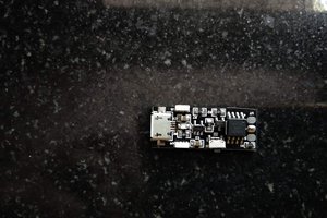
 Rupin Chheda
 Open Green Energy