 typecad
When the components arrived, I mounted the TCXO onto a breakout board and put it together on breadboards section-by-section.
TCXO 🡒 74HC4060N
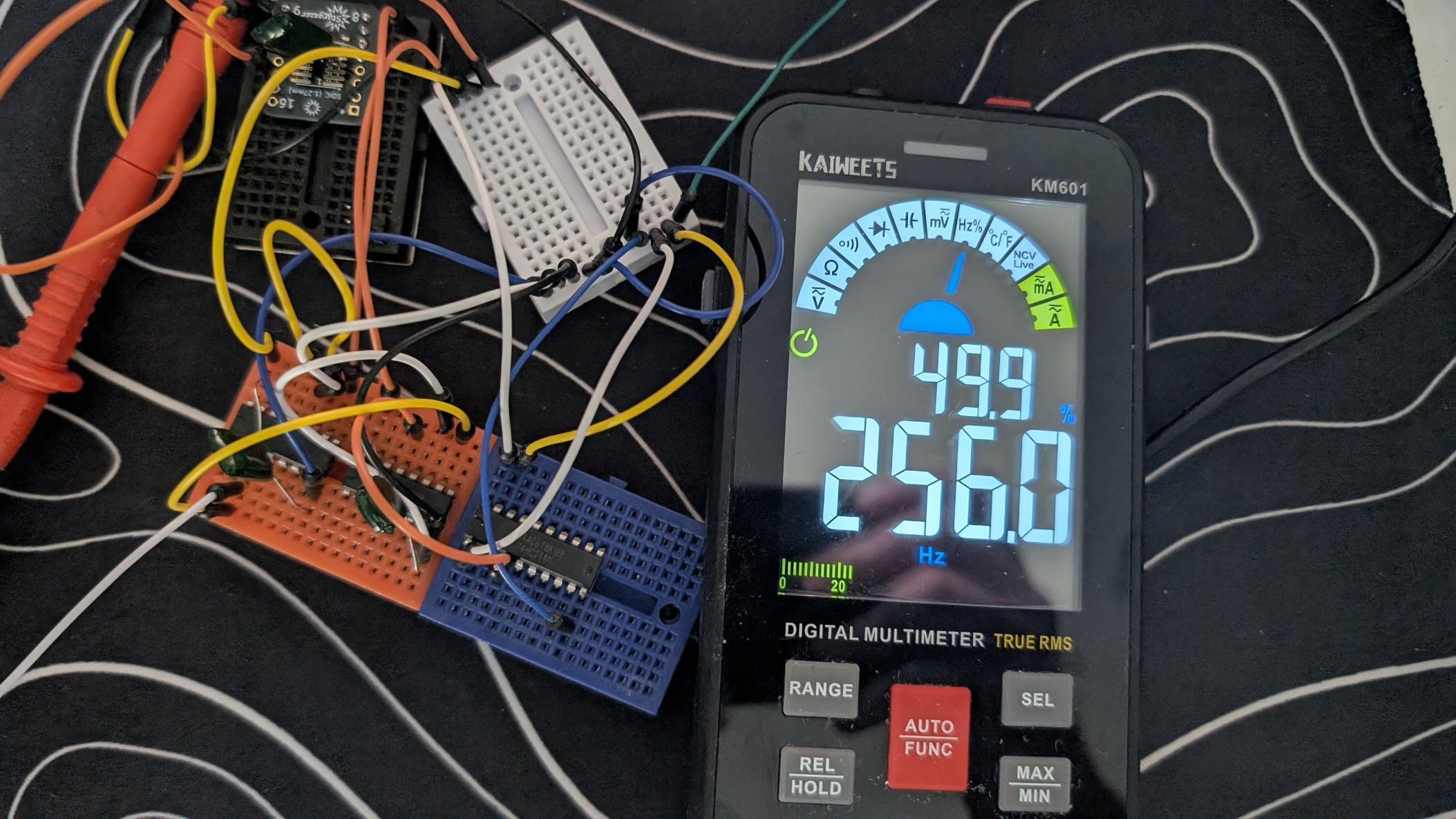
After I remembered to pull up the RESET pin, it worked. My MM measured 256.00.
74HC4060N 🡒 74HC4040N
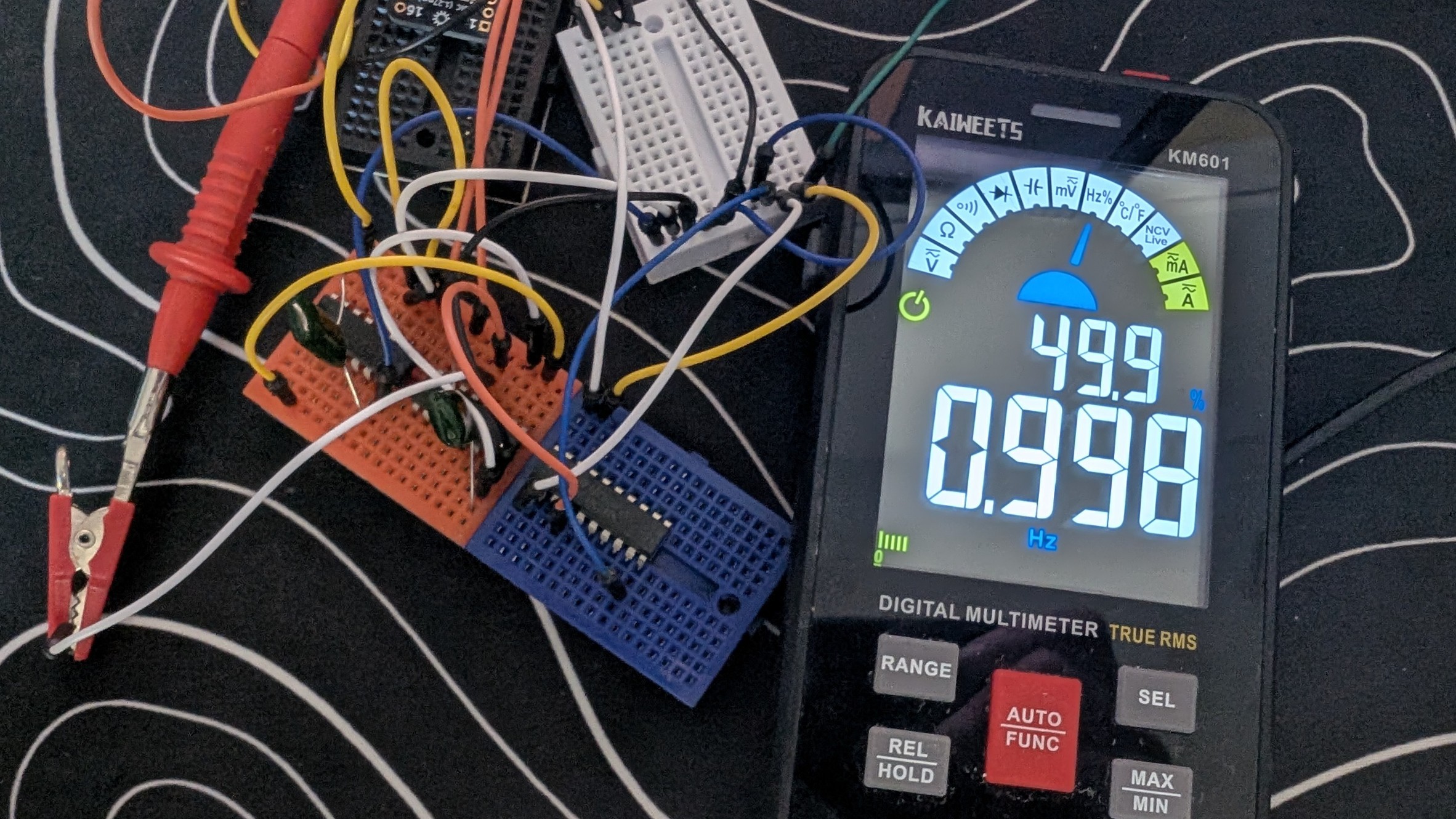
This one was confusing. The datasheet pinout doesn't match any of the symbols I could find. The typeCAD code also had issues with this. It provided the correct pin names, but not the correct pin numbers. After matching the typeCAD pin name to the datasheet name, I got the pin number and there I got 0.998 - 0.999 Hz.
74HC4040N 🡒 74HC244N
The same issues came up for this as well. The symbol was different than the datasheet. The typeCAD code had the correct pin names, so matching names to pins provided a nice driven 0.998 Hz signal that would light an LED.
Thoughts so far
At this point, it works. AI designed a 1 Hz blinking LED with very little input and guidance from me. The issues with the pin number vs pin names would have come up for me as well. The particular components that were used didn't seem to match the more common pinouts for these old components.
I did prompt the LLM 'validate U3 against [datasheet]' using the newly developed typeCAD MCP Server. Since LLMs can't read PDF files, it needs to be converted to text and that process doesn't result in easily understandable text:
- tables don't retain their lines or other formatting
- pictures are not extracted and 'viewed' by the LLM
- datasheets don't always have text that explains the pins names/numbers/functions
All of the above combined can make for some less-than-useful datasheets in terms of being understandable by LLMs. This is a great route to go down for future MCP server improvements though.
Discussions
Become a Hackaday.io Member
Create an account to leave a comment. Already have an account? Log In.