 Rupin Chheda
The Ballast Control Board is a plumbing project. In this board, there is a steel plate which is laser cut and everything mounts to it. Lets see this process step by step.
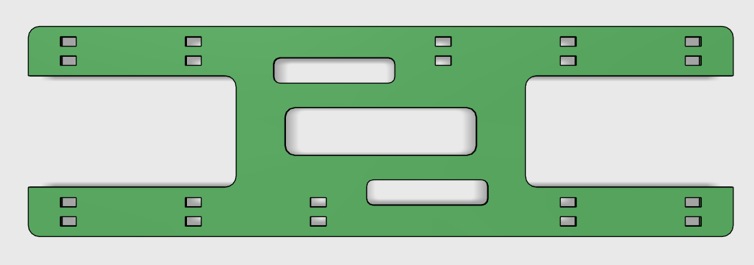
This is the plate for the Ballast Control. It measures 220mm x 66mm, small enough to fit in a pipe of 72mm ID.
You can find the pdf for this design in the files section. Download it, and get it laser cut on 2mm steel. 4mm acrylic is also good enough. Do not use MDF.
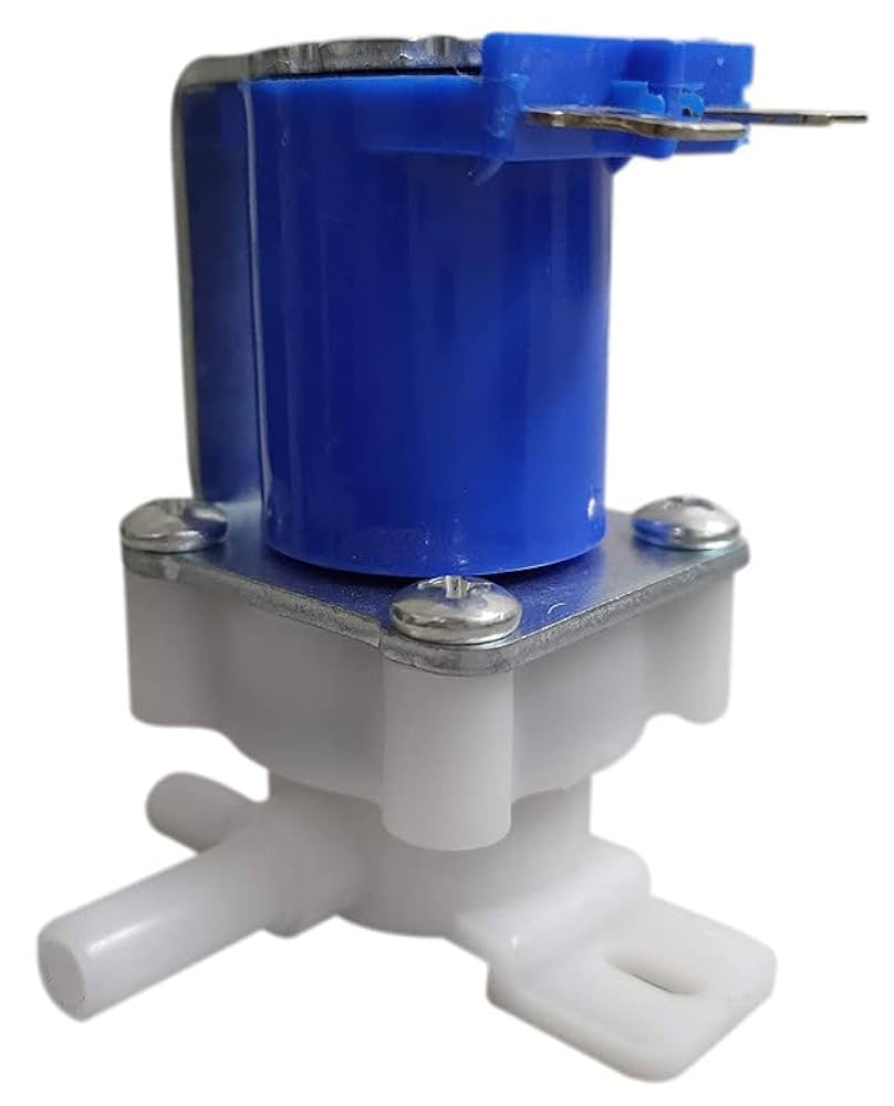
Step 2: Install the Solenoids.
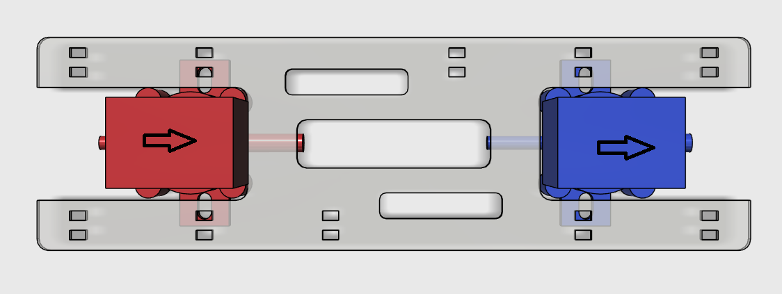
The Solenoids are electrically activated "air switches", that stop or let air flow. The solenoids are one way-valves too, they only allow a fluid ( air or water) to flow in one direction, often marked with an arrow on the body of the solenoid. We have to install the solenoids so that the arrows point in same direction.
The reasons will become evident to us in the steps further.
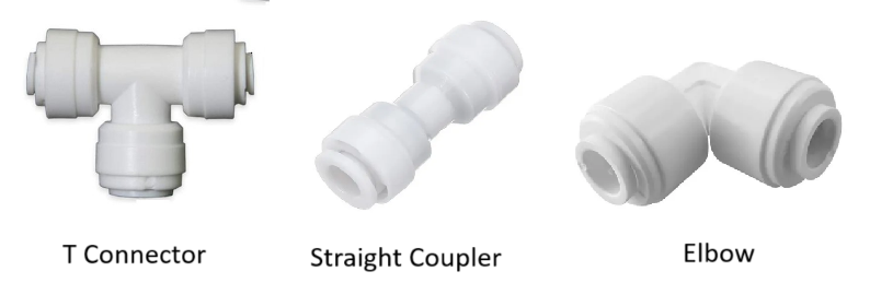
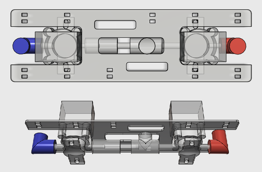
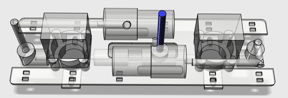
Step 3: Connect the Outlets with Push Fit Connectors
- Green is a T connector. The vertical outlet of the T is where the air will be moving in or out of the valves.
- Red is a Straight Coupler.
- Blue is 1/4" pipe which you can push fit into the T and Staright Coupler.
To understand the image better, we must know that only one solenoid is on at any point in time.
If you follow the arrows, it becomes obvious that the solenoid on the left of the image allows air to flow towards the T connector, hence it allows the air to flow out.
The solenoid on the right will allow flow of air to be away from the T connector and towards the right.
By placing the solenoids this way, we have achieved the air to flow towards and away from the T connector.

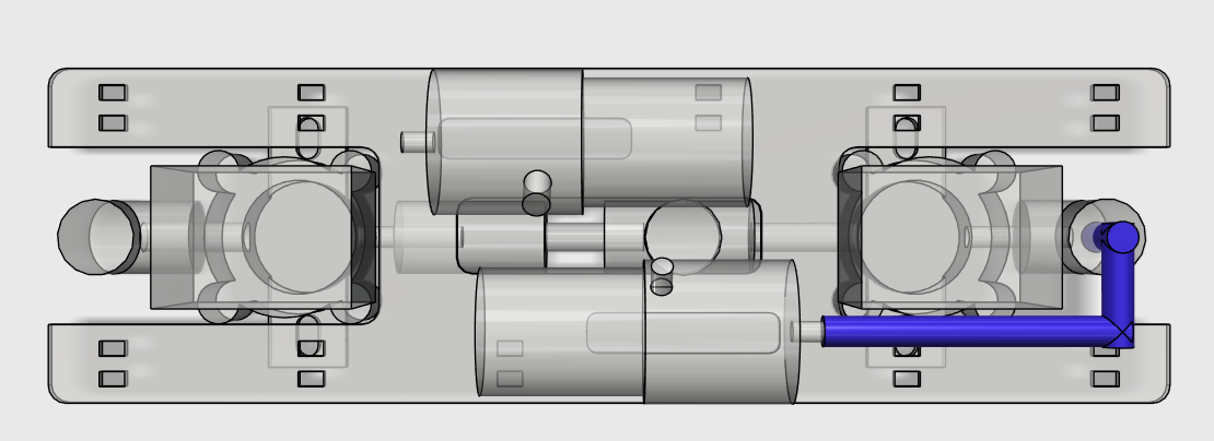
Step 4: Connect the Elbow Connectors on the solenoids
Push fit the Elbow Connectors.
The Pumps will be connected to the Elbow Connectors next.
Step 5: Install the Pumps. The are zip tied to the plate.
You will notice the pump has an inlet and an outlet. The inlet is on the side of the pump, the outlet is in the front of the pump.
Air will be sucked through the inlet, and exits out the outlet.
You can inflate a balloon, if it was connected to the outlet.


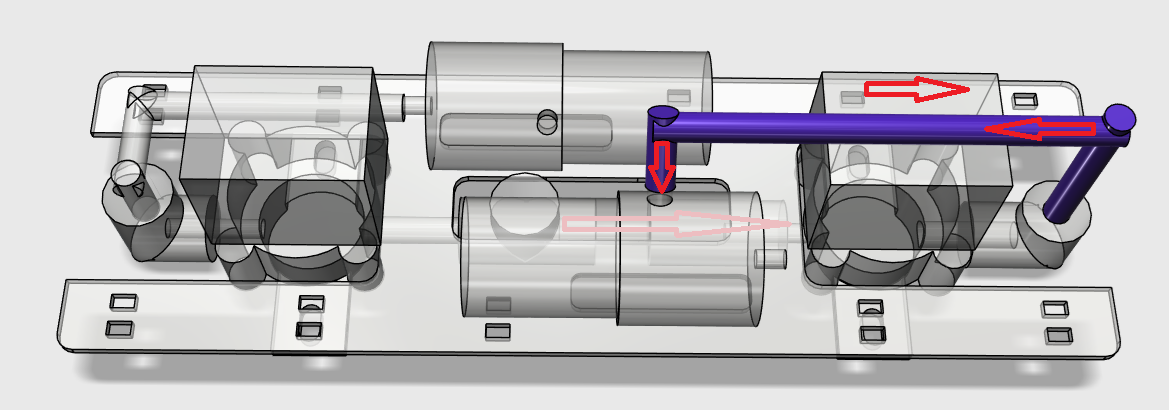
Step 6: Connect the Infator Pump
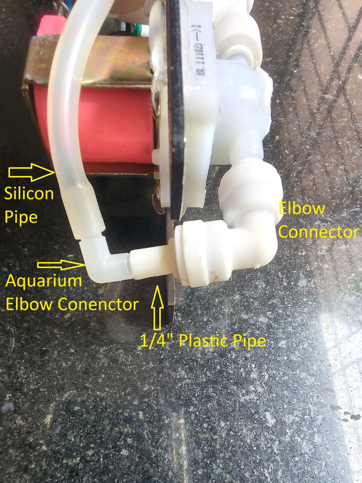
Use a Flexible Silicon Tube and Connect the Outlet of the pump to the inlet of the solenoid. This is where the elbow Connector is joined..
The red arrow represent the direction of the air flow when the pump and the solenoid are turned on.
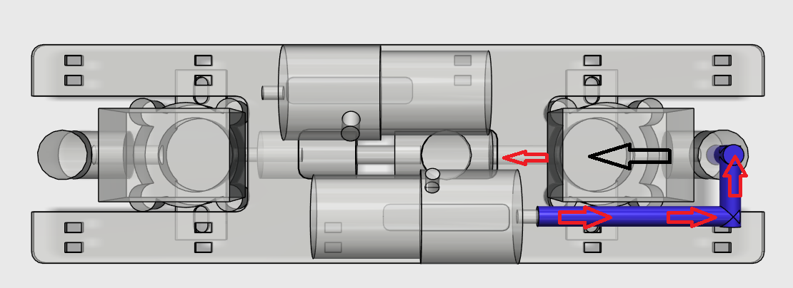
Step 7: Connect the Deflator Pump
Use a Flexible Silicon Tube and Connect the Inlet of the deflator pump to the inlet of the solenoid. This is where the elbow Connector is joined..
The red arrows represent the direction of the air flow when the pump and the solenoid are turned on.
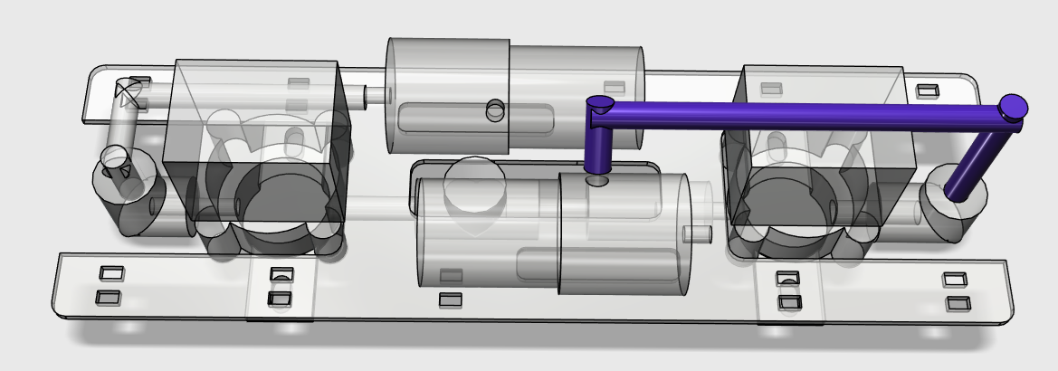

Step 8: Connect the Outlet Pipe


This ends the construction of the Ballast Control Plate. We will move on to testing this by soldering wires to all the devices one at a time.
Discussions
Become a Hackaday.io Member
Create an account to leave a comment. Already have an account? Log In.