 Rupin Chheda
The Body of the Submarine comprises of the Water Tight Compartment, which is made up of 75mm drainage pipe, and the Ballast, made out of 110mm pipe.
We build the submarine inside out, ensuring every joint made is water tight and leak proof under pressure. The ballast control board can help inject air at high pressure into any volume, and we can test for leaks by immersing the structure in water.
Step 1
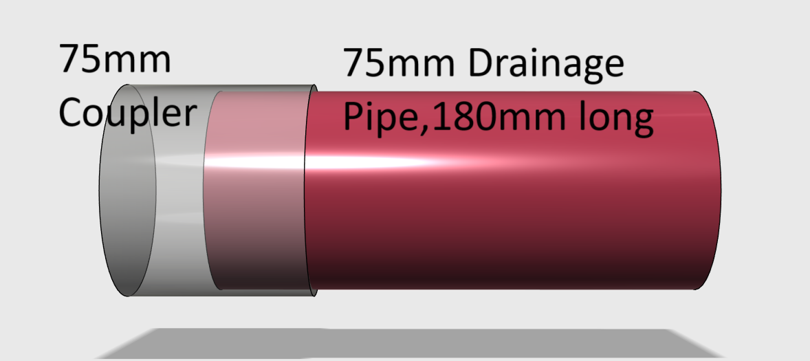
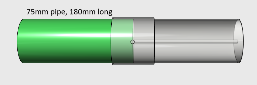
Get hold of the 75mm coupler and a 180mm long 75mm pipe. Join both of them using PVC cement.

Step 2
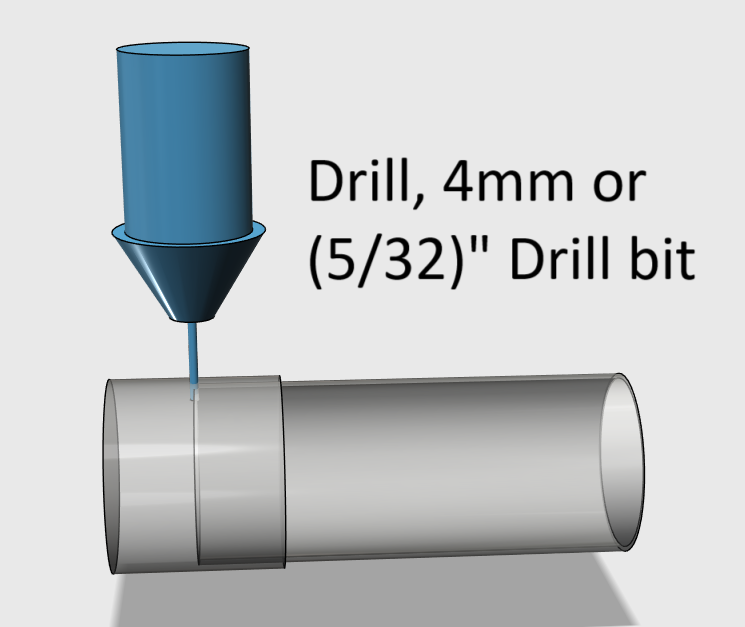
Drill a hole exactly in the center of the coupler. Use a 4mm or a (5/32)" drill bit.
Step 3
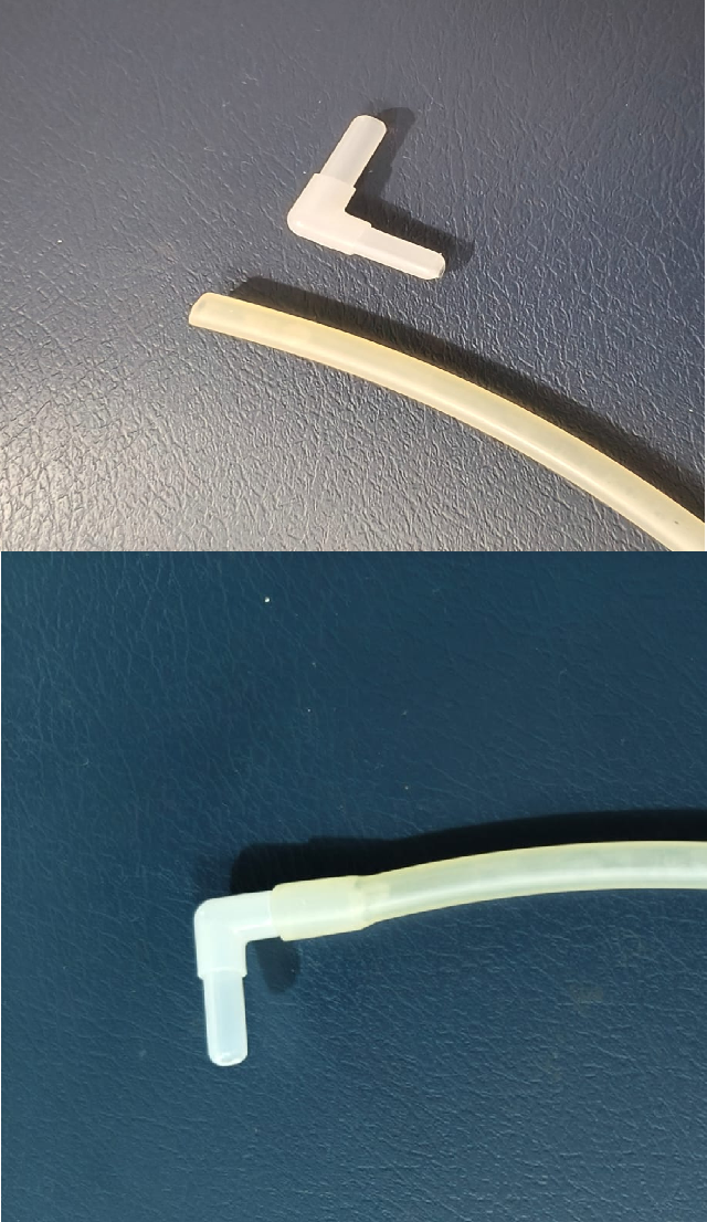
Create the air Inlet pipe using a 90 degree elbow connector and a silicon pipe. This is the path the air takes to and from the ballast.
Step 4
Insert this bent connector from inside the 75mm into the hole just created. Orient it such that the flexible pipe aligns itself in the direction of the 75mm pipe. Use CA glue to hold it in place. Make sure the silicon pipe hugs the inside of the 75mm pipe.
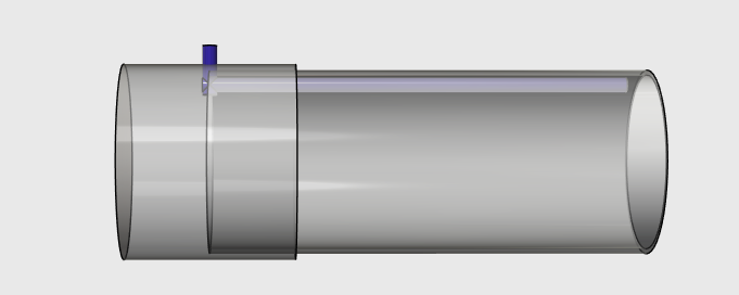
Try and push this connector inside, it should not budge, if it comes off, repeat step 4. It is important that this connector be in this place firmly. We will not get a chance to fix this connector again.
Step 5
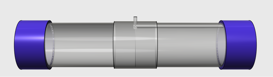
Glue another 180mm long, 75mm pipe to the other side.
Step 6
The water tight compartment is completed. Use two 75mm rubber caps to close both ends of the pipe. Connect a spare piece of silicon tubing and blow into the pipe. Immerse in water ( you can use a big enough bucket) and check if there is a leak. Fix all joints with two part epoxy until no more air escapes.
Step 7
Once the tests are completed that no more air leaks from any of the joints, we can start building the ballast.
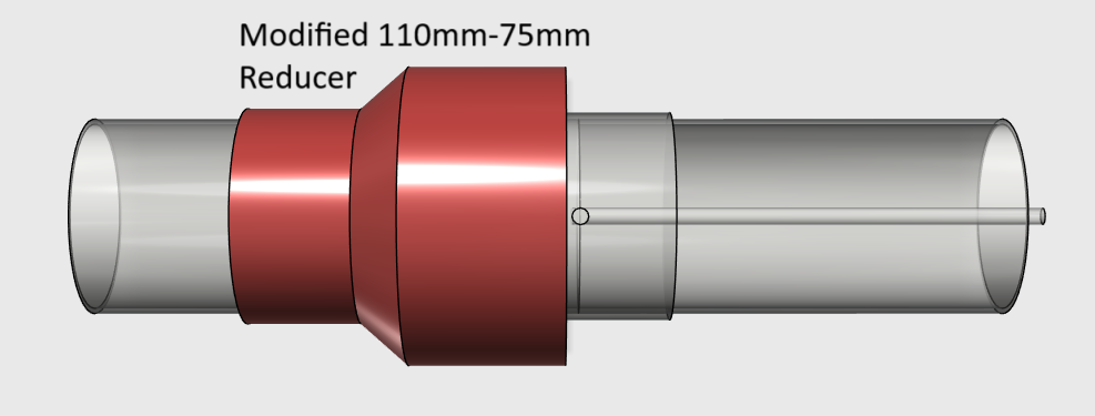
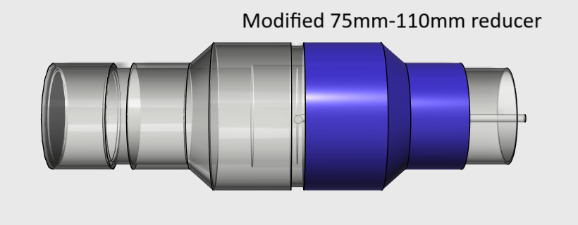
The ballast is made up of two inverted reducers which have been modified to slide on top of the 75mm pipe freely.
Fit the first reducer as shown. Its edge should just stop close to the center of the 75mm coupler.
Once you are confident its placed right, make sure you fit it permanently using pvc cement. We will test for air tightness once the entire ballast is completed.
Step 8
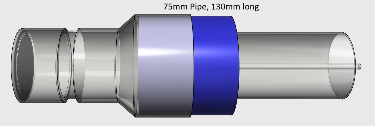
Close the left end of the 75mm pipe with a 75mm end cap. This will be glued with pvc cement.

Step 9
Lets start closing the Ballast. Fit a 130 mm long, 110mm pipe into the reducer as shown. Glue this with PVC cement.
Step 10
Slide in the other reducer from the opposite side, closing the ballast.
Step 11
If you notice, the flexible silicon pipe opens into the ballast. You can pump air into the ballast, with the other end of the silicon pipe to check for leaks.
Close all leaks with 2 part epoxy.
Cross Sectional View
In this view, we can clearly see the Ballast volume. Its the area between the purple cyclinder and the dark blue cylinders.
The pipe pops out of the dark blue cylinder and appears in the ballast.
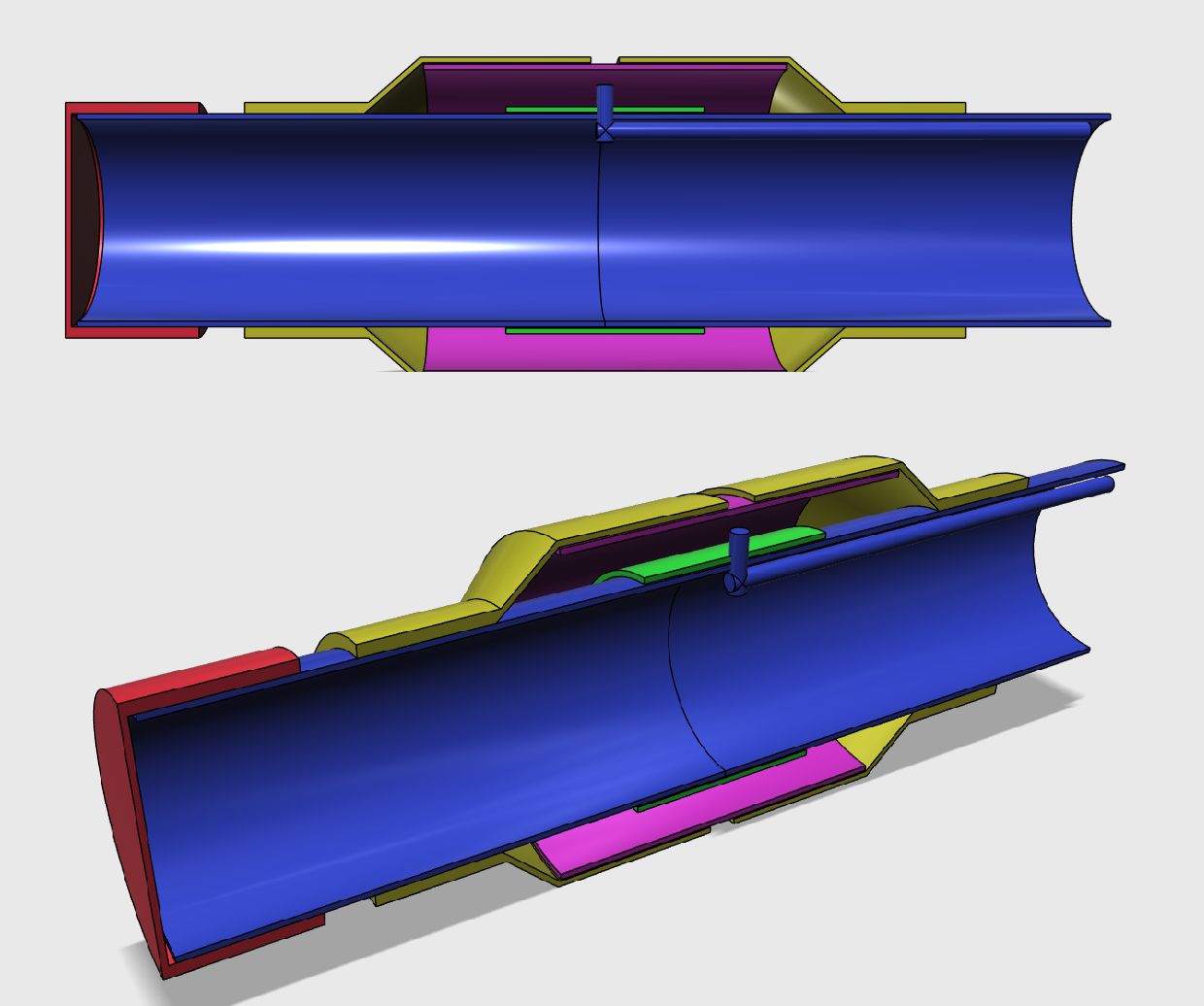
How will the water enter the ballast?
We will make a hole in the ballast at the bottom, diametrically opposite the small silicon pipe's entry into the ballast. This way, the water fills up the ballast from the bottom, and by the time the submarine has sunk, only 2/3rd of the ballast volume is filled up.
We dont want to make this hole until all tests of pressurisation and leak-proof-ness have been completed.
Discussions
Become a Hackaday.io Member
Create an account to leave a comment. Already have an account? Log In.