 Mr.50mm
This Build has a bit of Media attached to it for all who are interested.
This Camera has an Accompanying Set of Videos from my YouTube Channel, Mr. 50mm.
-The Channel - https://www.youtube.com/channel/UCirQEIw2y461w9w8tJNEM3Q
Camera Sacrifices Required:
Panasonic GF3 (must be functioning) (Don't forget to set the GF3 to "shoot without lens")
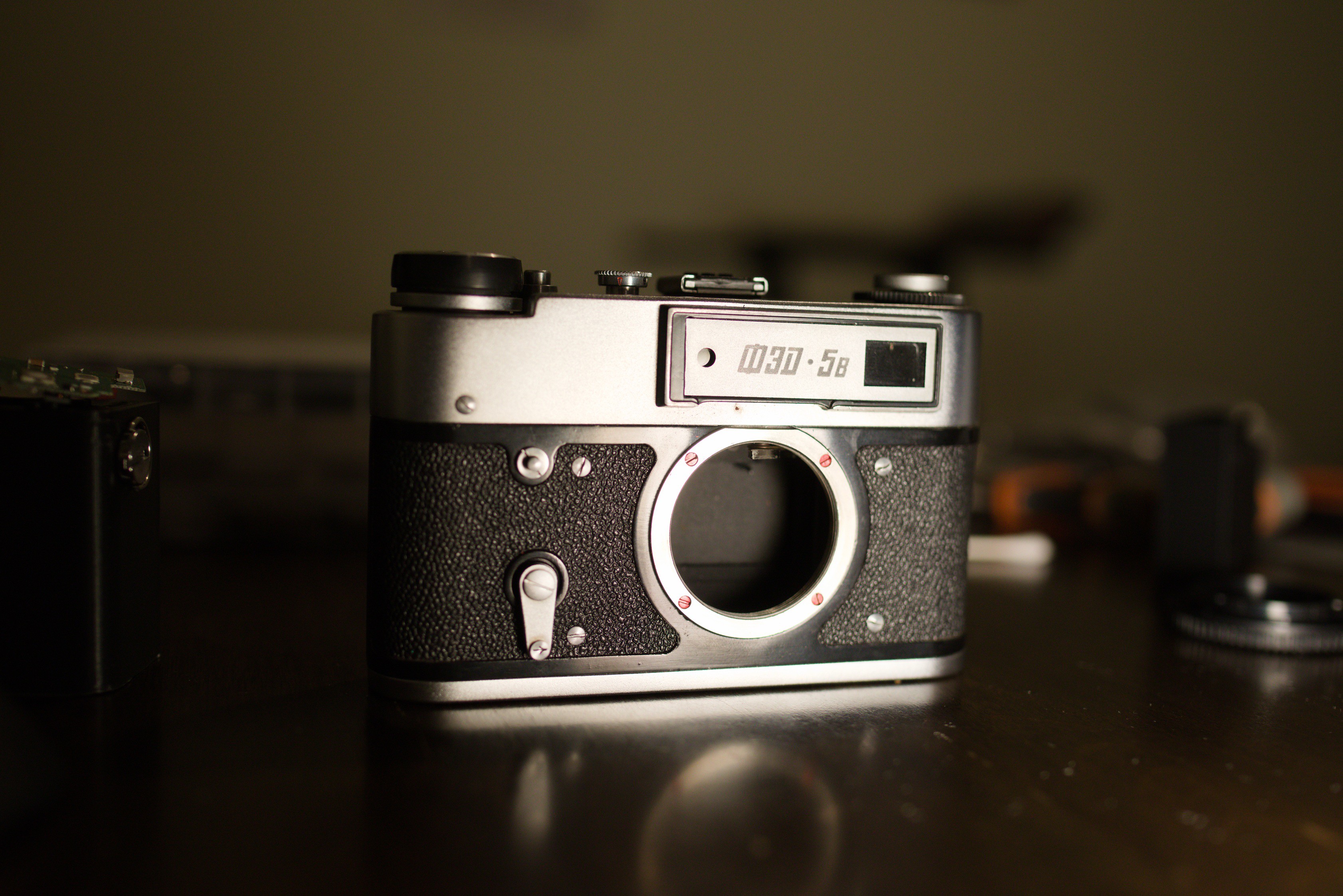
FED 5 Series Film Camera (Rangefinder must be functioning) The FED 5 variant must have the Diopter adjustment, I don't know if it works on the variants equipped with the projected frame lines.
Lens Adapter Sacrifice (M-Mount Only):
FotoDiox M to E Adapter - https://fotodioxpro.com/products/lm-sne?_pos=4&_fid=82ac7dba6&_ss=c
*** Warnings ***
The Panasonic GF3 electronics are quite fragile, in the making of a couple projects I have KILLED 2 Panasonic GF3s, use common sense when dealing with parts, don't leave batteries in, don't grab parts with metal tweezers with batteries in, ensure all connections are seated properly and locked in. Ensure there isn't any excessive strain on any PCBs.
*** Warnings Over ***
Build Caveats
Before you get started, be aware this is still a work in progress and there are still things that haven't been fully addressed, the main things that come to mind are the following:
1) Rangefinder coupling, I am still finding that even with the newest variant changing lenses results in something changing between lenses that causes the rangefinder to become inaccurate for the new lens. Initial thoughts were that it was related to the flatness of the rangefinder mount, but I fear there maybe other variables at play, the new mount did improve things but adjustments should be made if lenses are being swapped. If you are only planning to use 1 lens or seldom are going to be switching than this maybe ok for you.
2) There maybe light leaks on the build, I did generally have overlapping pieces going over seams for a lot of the camera so generally it shouldn't be a big issue, but I never bothered really doing an in-depth look once the design was a bit more settled down. I also didn't want to just tape everything up.
3) I never ended up addressing the third mainboard mounting screw, as of now the mainboard is still only supported by 2 screws on the camera's right side. So far none of my cameras have had any issues
4) When doing battery swaps the SD card MUST be removed the battery latch tab will push up against the SD card if you leave it and that could damage things. Always remember this.
Tools Required
Soldering Iron (to de-solder 2 lines) (cutting them will probably also work)
1/4"-20 Tap
M2 Tap (not that required, but nice to have)
Hot Glue Gun
Tweezers
Right angle cutter
Flathead screwdriver set (Jeweler's set or Electronics' work set) (1 must be at most 1.25mm across to fit into the groove for the grub screws of FED 5 finder eyepiece)
Phillip's Head Screwdriver (Jeweler's set or Electronics' work set)
(Any driver for whatever screw set you buy)
Scissors
Small Pliers (specifically for magnet installation)
Dremel With cutting Disk/Grinding (ONLY FOR M-Mount Build)
Heat Resistant Gloves (ONLY FOR M-Mount Build)
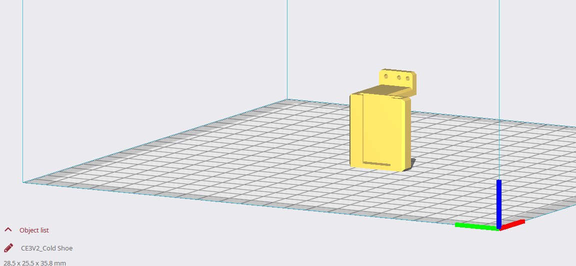
Here's also where I'm going to put the configurations for the prints
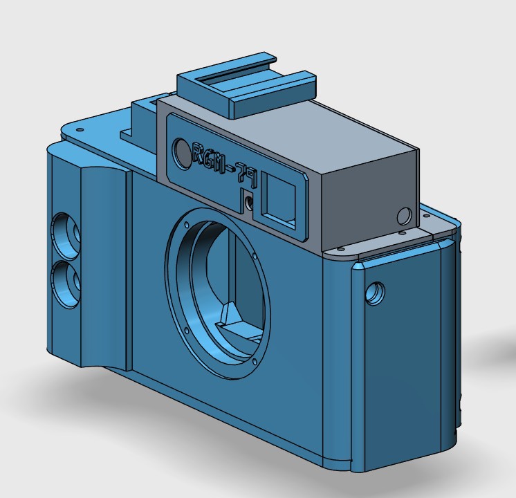
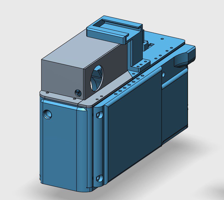
Print option 1 - Rangefinder, Yes Front Grip, Yes magnetic screen cover. Cold shoe optional
Print the Following
RF Body Front Grip Mount Screws(4x Tripod Screws).stl
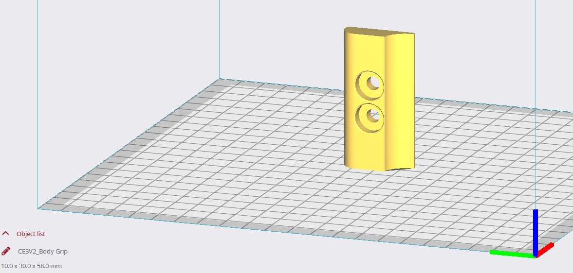
Body Grip.stl
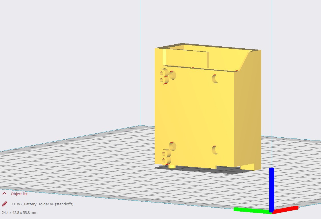
Battery Holder V8 (standoffs).stl
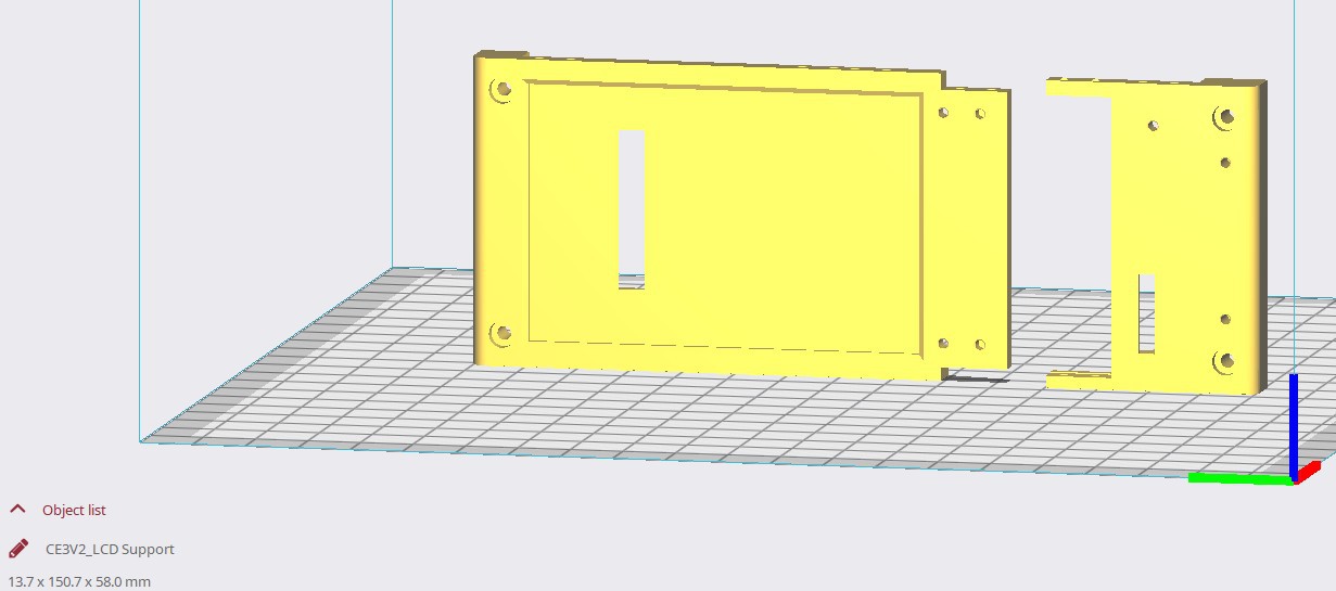
LCD Support.stl
Rear Button Panel Support.stl
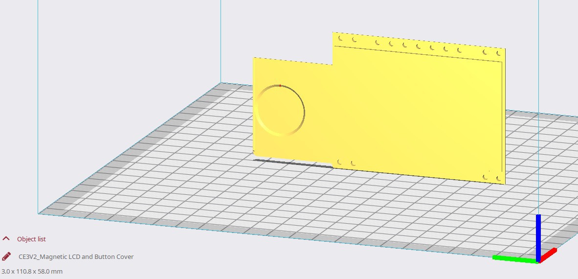
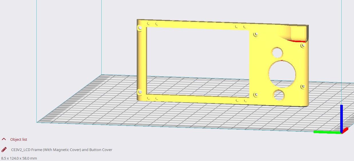
LCD Frame (With Magnetic Cover) and Button Cover.stl
Magnetic LCD and Button Cover.stl
Batt Cover 2.stl
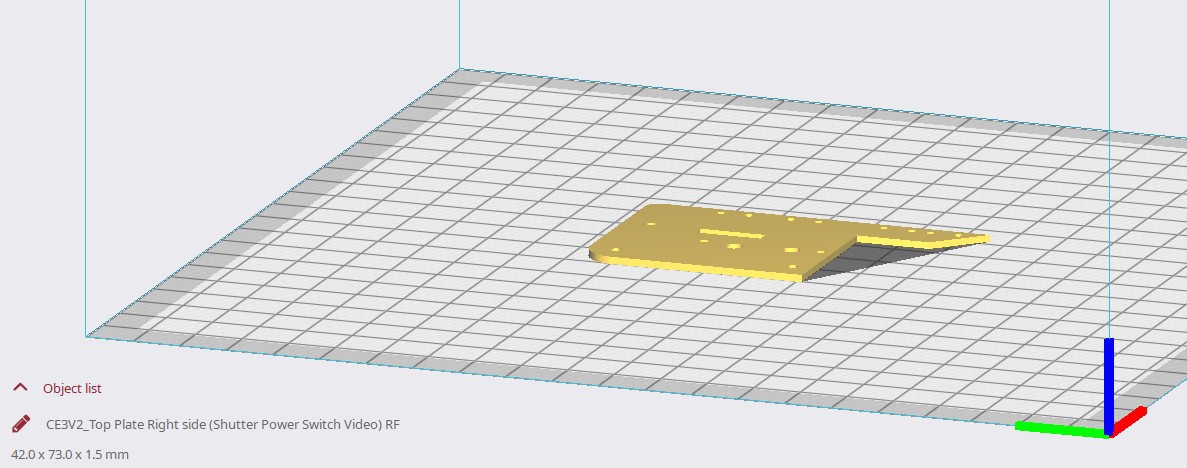
Top Plate Right side (Shutter Power Switch Video) RF.stl
Shutter Button.stl
Video Button.stl
Power Toggle (Thin).stl (Or Thick)
Shutter and Video Button enclosure.stl
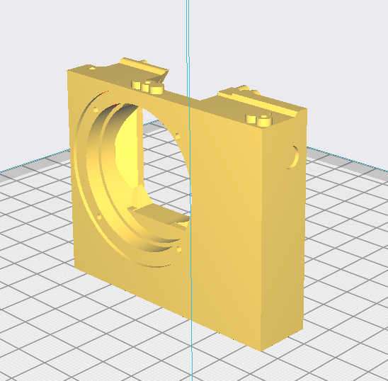
Rangefinder Eyepiece Cover plate.stl
Rangefinder...
Read more »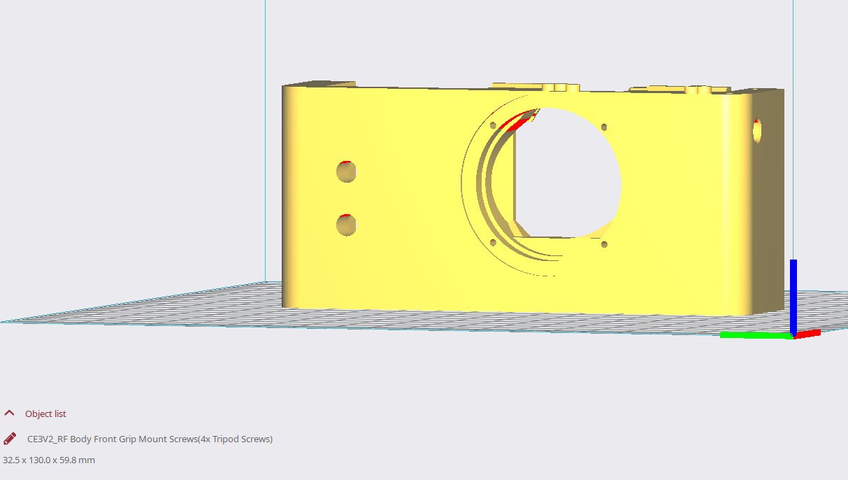


 Steve Schuler
 Victor Frost
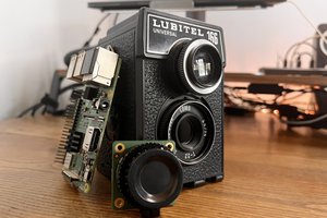
 Gradivis
 John
John