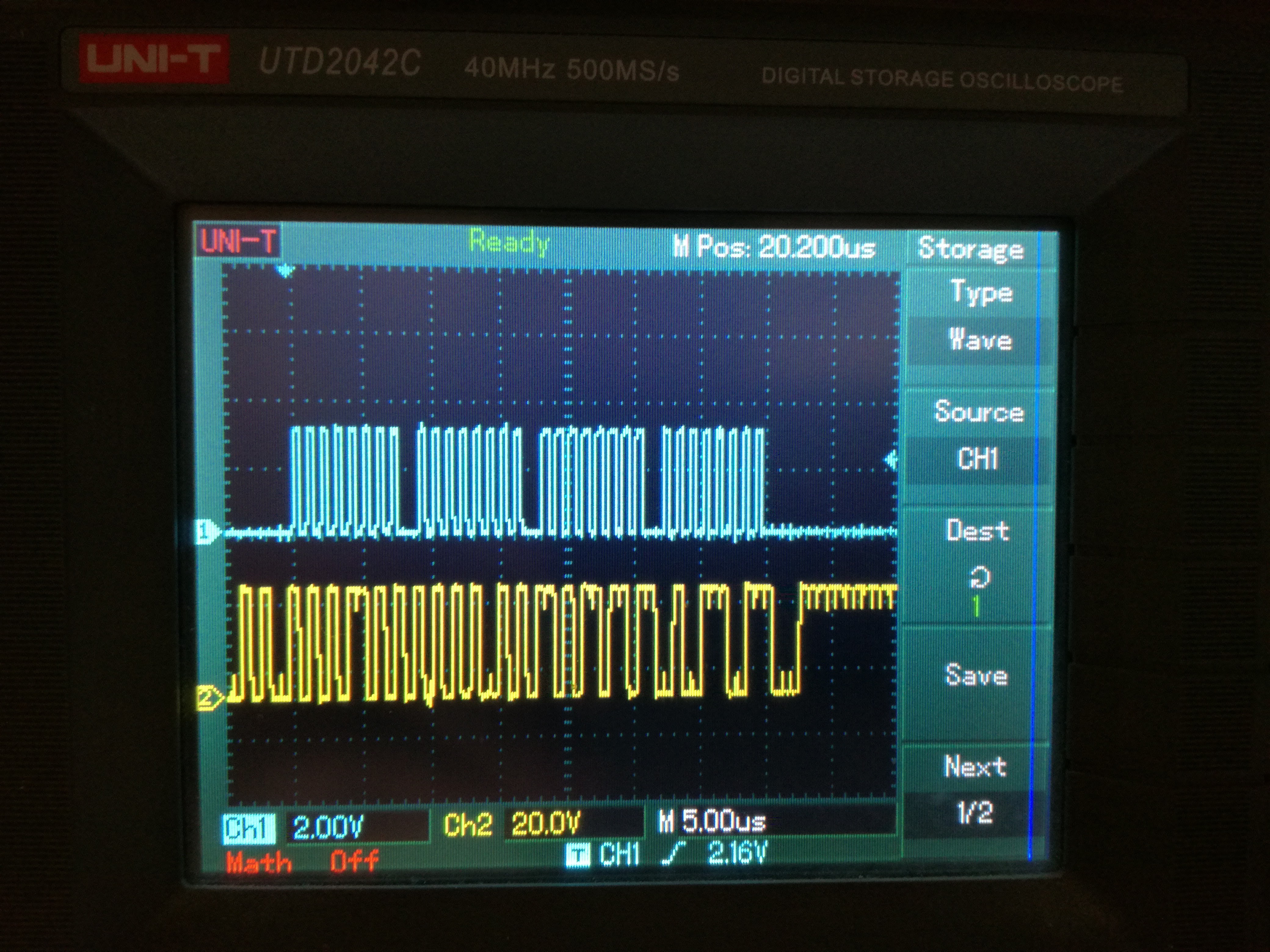
It really took a long time to get the damn MAX chip working. Although I made it set MUX line high or low, I couldn't make it talk to me via SPI. On the scope, this line looked like nonsense:

In the process of investigating, I managed to burn 3 Teensy boards and 2 MAX chips. Don't ask how. I consulted tech support of Maxim Integrated as well. They were really friendly and prompt reacting (thanks Mohammed). But, before I got the answer from them, I decided to try one thing.
MUX bits are distributed in two registers. MUX[3] is in reg 5 while MUX[2:0] in reg 2. My initial code was writing reg2 first and reg5 later. For no clever reason, I decided to switch the order of writing. Guess what? Problem solved.

Aaaargh!
I'm using SPI read to get some data out of MAX2871. These are for chip temperature, VCO tuning voltage, and autoselected VCO number. During the development I found out that ADC that reads VCO voltage and temperature must be set and reset after each readout. Otherwise, it won't read properly.
 Pero
Pero
Discussions
Become a Hackaday.io Member
Create an account to leave a comment. Already have an account? Log In.
Please send me code i want to genrate Band 860 MHz to 970 MHz but falil
Pleasesebd code for 433 mhZ frequecy also I shall be thank full i am using Ardunio
to orogram MAX2870 Board
Are you sure? yes | no
Well done - you got their in the end. I managed to burn out one of my expensive VGA chips yesterday - a small pool of liquid could be seem erupting from the bottom right corner. I don't think this is normal :)
Are you sure? yes | no
thanks, but, what?? liquid coming out of chip??
Are you sure? yes | no