Pero
Pero-
HW fixes
06/09/2017 at 08:25 • 2 commentsAfter my honeymoon trip and triathlon race, I finally found the time to fix those bugs. Broken LDO was replaced by some similar 3V3 LDO in SOT 32-5 package from an older project. It did the job well, and 3V3 as well as other voltage, were present at their places.
RF detector on the other hand was a bit more difficult thing to find. Log detector LMH2110 that I lost was available only from Digikey, that would charge me additional $20 for shipping on $1 of chips. The retailer that has lower shipping costs in my country, RS components, only offers another chip in the same package with the same pinout: LMH2120. Thing is, this is a linear detector. But, since it was cheaper solution, I decided to give it a try. I'll worry about log/lin issues later.
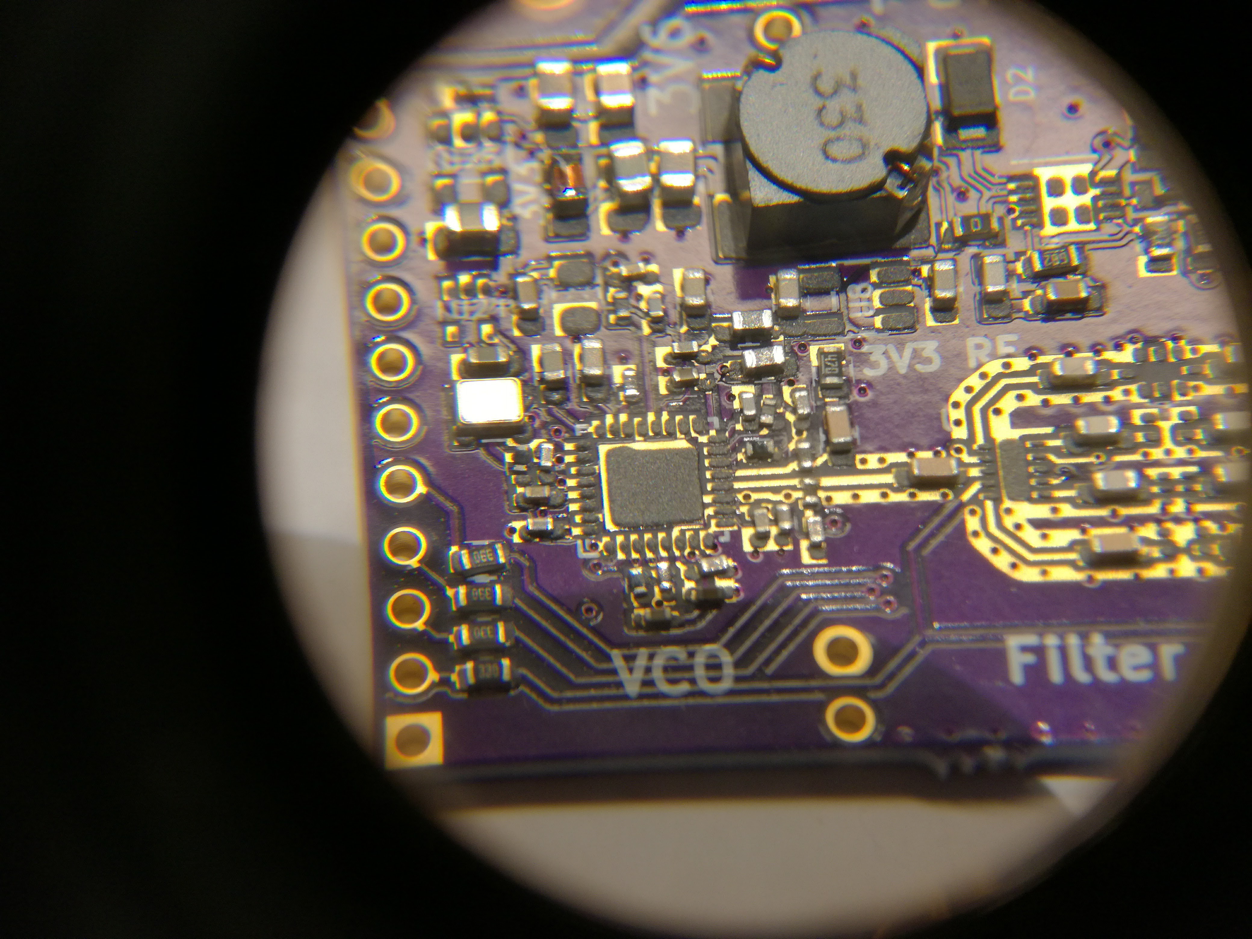
It was the same pain soldering it as before. However, I didn't use hot plate, although I planned to do so. I've put a bit of solder on those tiny BGA pads and covered them with flux. Then, I placed the chips, carefully under the microscope. And finally, I soldered them using the hot air gun, high temperature but very low air speed. I usually don't use microscope when working with SMT, but for chips this size, it was detremental. In any case, chips got soldered, though I'm not 100% sure if they're placed in the right way.
-
HW Bugs
05/12/2017 at 09:04 • 3 commentsThe soldering process went on mostly well, no tombstones, no misplaced components and no excesive solder...however, some bugs were found and caused me a couple of hours of annoyance:
- 3V6 and 5V voltages missing. For some reasong the switching power supply L7980 didn't deliver the said voltage. After some time of examination, I found the root cause, and it couldn't have been more stupid than it was - feedback resistors R60/R61 and R62/R63 were converesely set. So, instead of 5 or 3V6 volts at the output, the voltage divider was set to 0.75V. The reason of this folly is that in my Assembly Drawing the resistor designators were misplaced. Replacing the said resistors solved the problem.
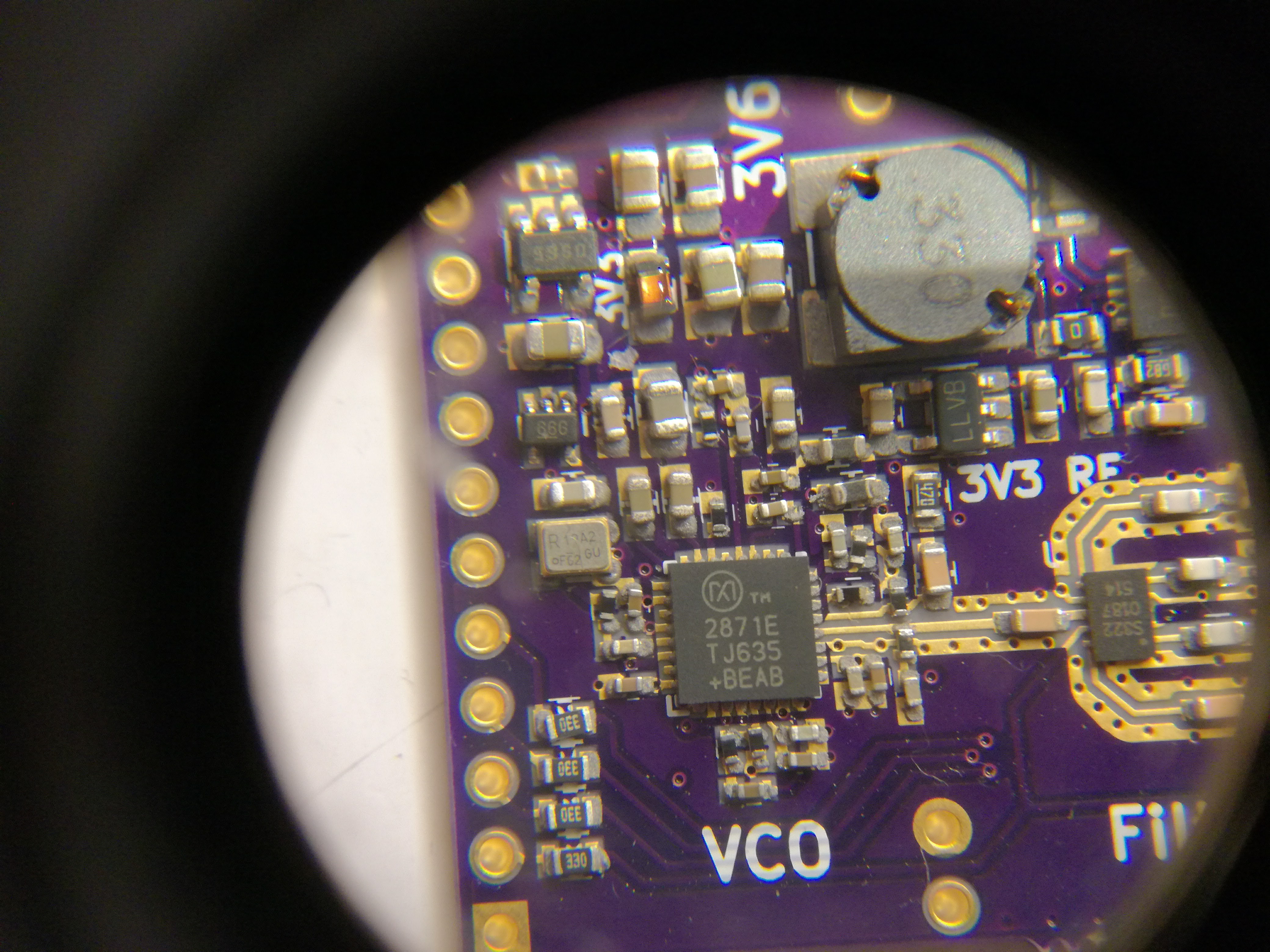
- Short circuit at 3V3 RF. After I got SMPS to work, I noticed increased heating of the chips. Soon, I realize that 3V3 at the PLL of MAX2871 is shorted. To find out the location of the short, I lifted the U8 chip (LP5907) and broke it by accident. But at least, I've found the cause of short circuit. Under the MAX2871 chip there is a ground pad and 3V3 trace very close to it. For some reason, solder mask doesn't cover it completely. So, during the soldering, some paste went over it and made a short. Reworking the MAX2871 solved the problem. However, I've lost LDO chip and have to replace it now.
- 6-ball BGA didn't solder. This one was really anoying. The small RF logarithmic detectors LMH2110 didn't solder to their place, so I needed to do it manually. First, they are increadibly small (IC size smaller than 0603) and it was Sisyphus work to put them on their place. I managed to loose two of them just by clasping them a bit too hard with my tweezers. Second, I couldn't solder them easily because, I assume, the solder balls are lead-free. I wasn't able to heat them up with my hot air gun (nor reflow oven) because the air flow was set too low because any higher air flow would blow them away :/. I plan to use hot plate next time when I solder them, that is, when the new batch arrives because I lost all those that I had :(
- Filter lost. Simple as that, I lost the filter LP0603A1880ANTR.
These are all bugs I found so far. I examined the board and believe that it main parts should work properly. I could test out the VCO, attenuator and switches, but I cant solder the Teensy on board before all my reworking is done. So, when new detectors arrive, I'll give it a test try.
-
Day of solder
05/07/2017 at 16:21 • 0 commentsFriday evening is fun evening for some, but soldering evening for me. In the coworking space with my beer and curious passerby I patiently sat and manually placed every single component, ruining my eyes and hurting my back. This is how the process went:
- Placing the stencil:
Positioning stencil above the pcb manually is probably the most tedious work there. It is never positioned perfectly and if one side seems right, the other is most certainly wrong. In this job your best weapon is patience.![]()
- Applying solder paste
At the same time carefully, like holding a panda shaped snowflake and yet firmly, like holding the door against the horde of Orcs, you have to apply the paste. Be sure to wear the clothes you like the least.![]()
- Pick'n'Place
Meditation and life contemplation. Wining imaginary quarrels. Best jokes you'll ever think of.![]()
![]()
- Burn it all
very slowly. In my homemade solder oven. Solder process went OK, no tombstones were created but I still wasnt't really happy with the quality of the solder joints. It seems like there was not enough solder paste applied and I'm worried about quality of connections.![]()
- Placing the stencil:
-
Everything arrived!
05/02/2017 at 21:06 • 0 commentsSo, today I received the PCBs from OSH park, the last thing I was waiting. It has been a month since the order. What to say about it? DigiKey parts arrived within two days, OSH Stencils arrived within a week and pcbs within a month. See the geometrical progression there? I assume they would arrive sooner had I payed for a priority shipping, but this is a hobby project, therefore no rush. Now, to the lab and get on with soldering!
![]()
-
Everything ordered
04/03/2017 at 20:57 • 0 commentsToday, I've completed all orders: PCBs (OSH Park), stencils (OSH Stencils) and components (Digikey). These are the total costs:
PCB (4 layers, 3.5"x1.4") €44.20 Stencils (3mil kepton, 1" margins) + shipping €14.50 Components (ICs, some inductors) €55.50 Total €114.2 Not a cheap hobby. Still, it's in the price range of cheaper RF synthesizers obtainable on Alibaba or Ebay. However, this synthesizer offers on board power meters that can be used for level control as well as scalar network analysis.
-
Layout review on Reddit
03/30/2017 at 08:38 • 0 commentsAfter finishing the layout I aksed for some review by PCB experts/enthusiasts Reddit. A nice and interesting discussion followed and made me redesign some things: via annular rings, position of decoupling capacitors, repour of gnd planes etc. I'm going to give it a double check once again and send it to fabrication to OSH Park before the weekend.
P.S. I've uploaded the new screen shots in "Files" section, but Hackaday.io keeps the old screenshots for some reason. Maybe because of the same filename?
-
Modified coupler
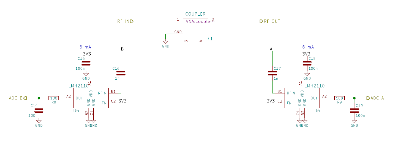
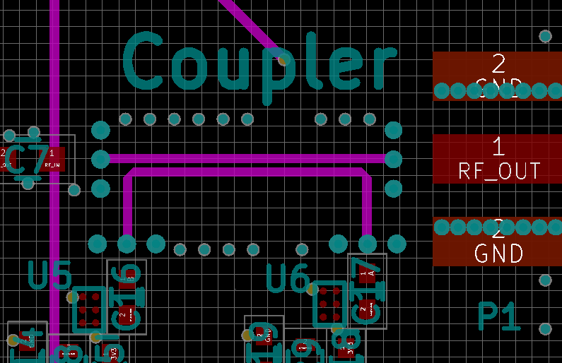
03/28/2017 at 08:41 • 0 commentsI have modified Henrik's original directional coupler. Instead of two couplers in series with terminated isolation ports I decided to have only one coupler with RSSI detectors on both coupled and isolated port. This way I hope to be able to measure both output and reflected power from the same component, which is useful for VSWR estimation.
![]()
![]()
-
Layout finished!
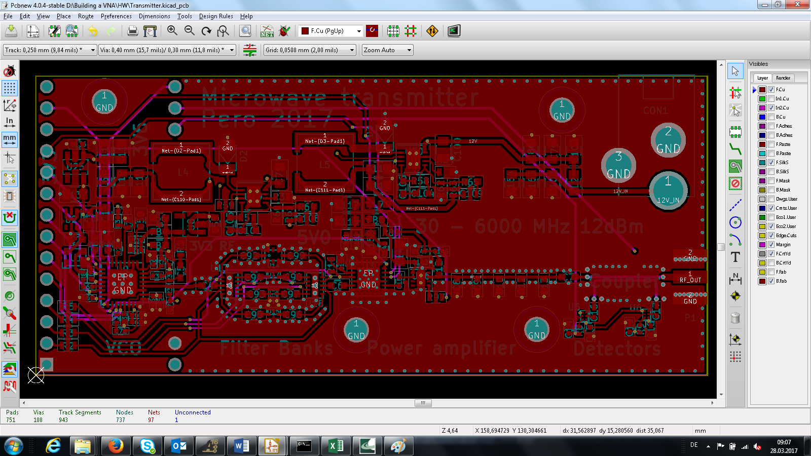
03/27/2017 at 20:20 • 2 commentsToday I have finally finished PCB layout of the transmitter! Hurray!! It is small victory as it was the first time I dove into annoying world of Kicad. Kicad is a great tool, I guess, and as anyone here on hackaday.io I really do support its open source/freeware culture, but my gosh is it annoying when you have to google for tricks on how to do basic via stitching. But, now as Eagle has gone to subscription mode, Kicad is a must know for makers and one of the reasons I did this project in Kicad is to finaly learn it.
![]()