0%
0%
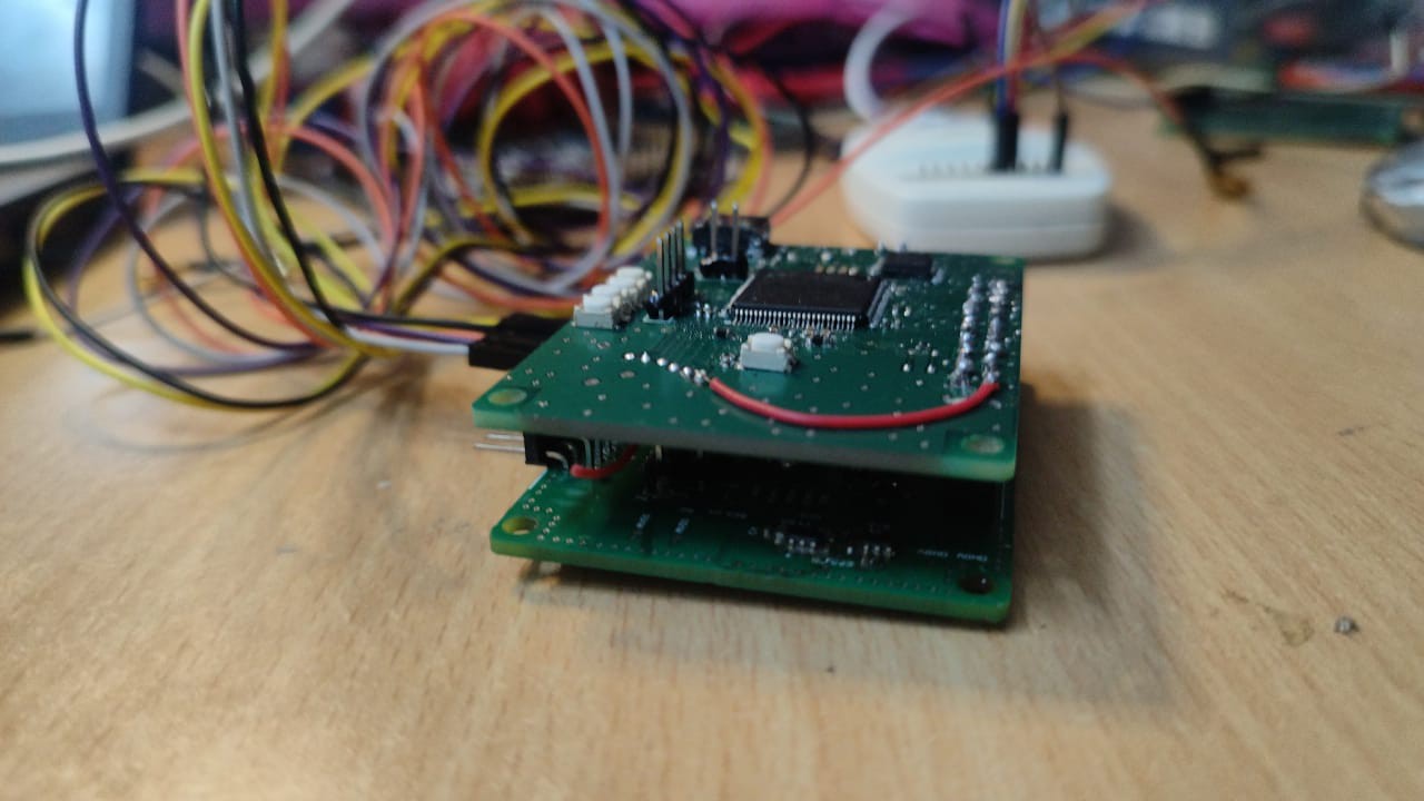
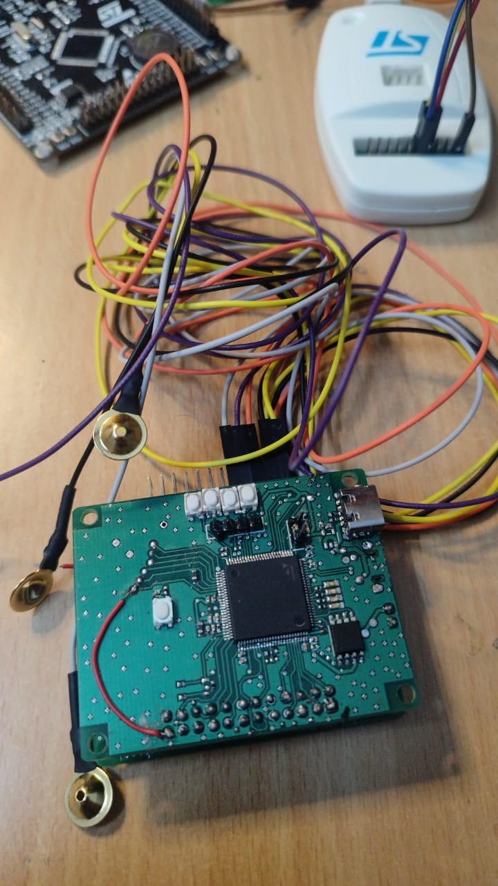
ADS1299 breakout board
Custom ADS1299 8-channel EEG breakout board
 Aditya56h
Become a Hackaday.io member
Already have an account? Log in.
Just one more thing
To make the experience fit your profile, pick a username and tell us what interests you.
Pick an awesome username
hackaday.io/
Your profile's URL: hackaday.io/username. Max 25 alphanumeric characters.
Pick a few interests
Projects that share your interests
People that share your interests
 maehem
 WingTechCorner
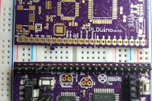
 Jeremy g.
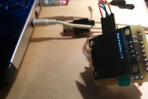
 Jakub Piasecki