 burble
The first step in the project was to quickly get a prototype running to test the concept and get an initial idea on where some of the challenges may lie
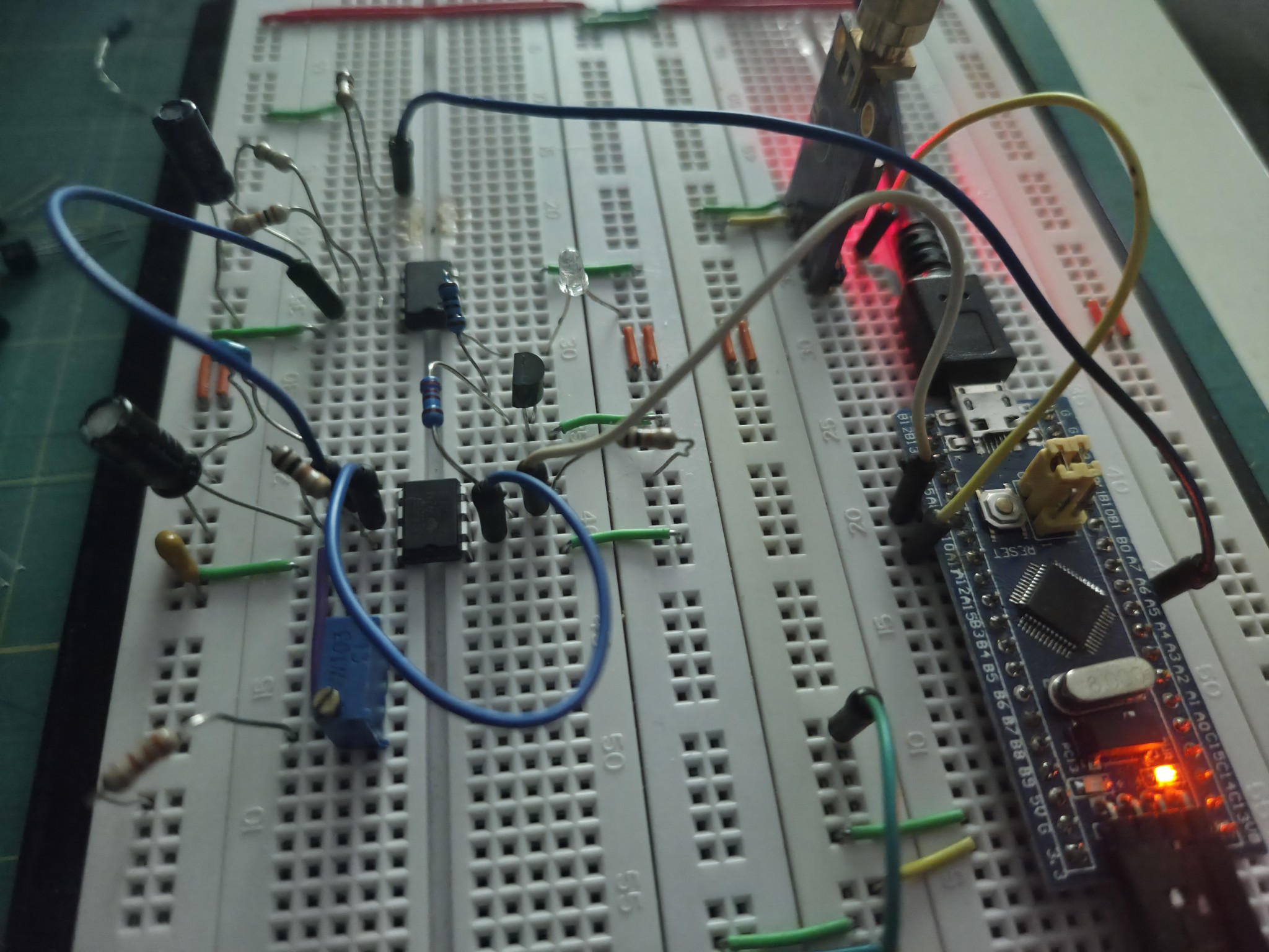
PWM Filtering
The MCU runs at 3.3v and uses a 16bit timer for the PWM signal, therefore providing 65k levels over a 3.3v range. The 555 however is operating at 5v and a full 3.3v range is way too much, so a simple PWM filter was chosen to shift up the PWM voltage and narrow the range:

The filter provides a lower bound of the PWM at ~2.24v and an upper bound at ~3.5v with a resolution of around 19uV per PWM step.
Success !
The prototype was able to demonstrate management of the 555 frequency using the control pin and a basic PID was able to bring the frequency to 1 hz:
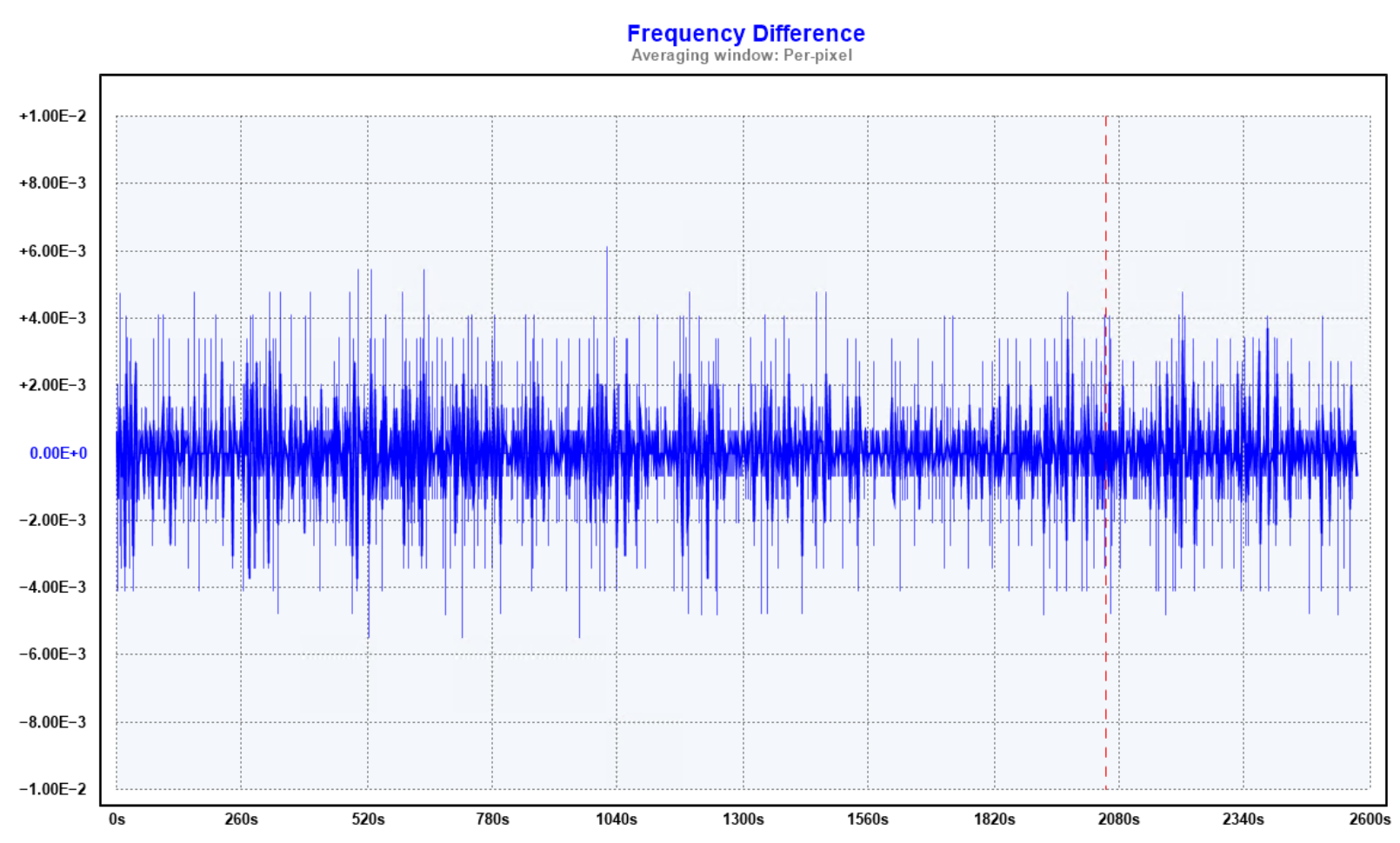
Approximately anyway, it's pretty noisy and we should be able to do better.
The first problem also became apparent pretty quickly ...
Powering the prototype via the microcontroller USB connection wasn't going to be enough and a separate power supply with regulated voltage was going to be required.
Discussions
Become a Hackaday.io Member
Create an account to leave a comment. Already have an account? Log In.