 burble
The second prototype makes a number of improvements over the first
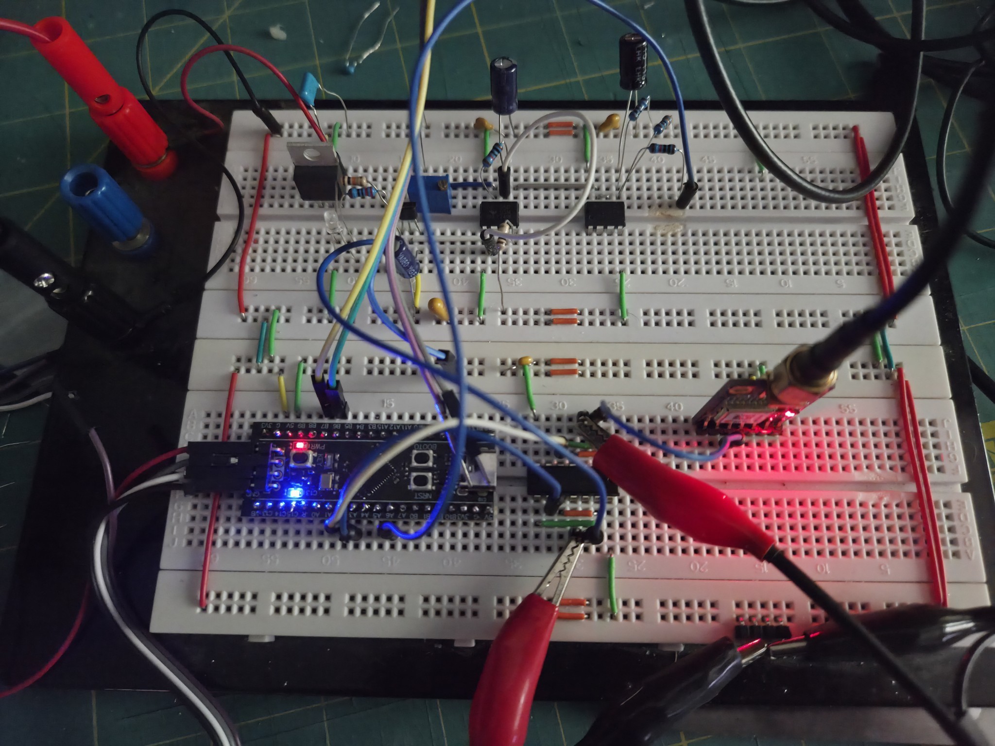
- The stm32f103 (Blue Pill) is swapped to an stm32f411 (Black Pill). The stm32f411 has a 32-bit timer allowing it to count a full 1 second period of 100 million ticks without overflow. This considerably simplifies the timer code and avoids potential race conditions that can occur with a 16bit timer and dealing with overflow.
- Power is now provided by a 5v LDO regulator driven from my bench power supply rather than the USB socket of the microcontroller. The flipside to now having plenty of spare power is that I can no longer use the USB serial on the microcontroller and have to add a serial to USB converter and output debug via the USART. The blue/black pill designs do not isolate the USB socket so you are unable to have both the USB and an external 5v supply connected.
- A 74AC14 Hex Schmitt trigger has been added to buffer the PPS from the 555 and GPS receiver. The 74AC14 allows adding led's and measurement probs without overloading either of the sources.
- With the initial prototype, it became clear that additional PWM resolution would be required so the PWM filter was tightened a bit
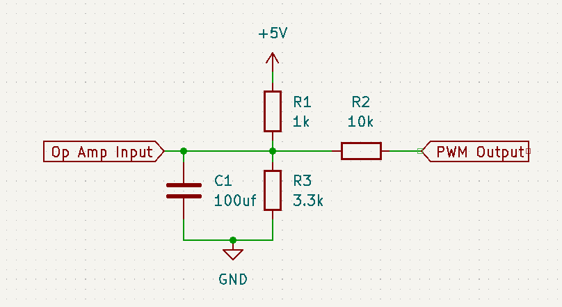
The PWM control voltage is now roughly 3.64v to 3.84v with a resolution of 3uV per PWM step.
- The first prototype software had 16bits of resolution when comparing the 555 and GPS frequencies. This was also increased to 24bits. This should be way overkill, but I've paid for all those bits and I'm going to use them.
The result is good
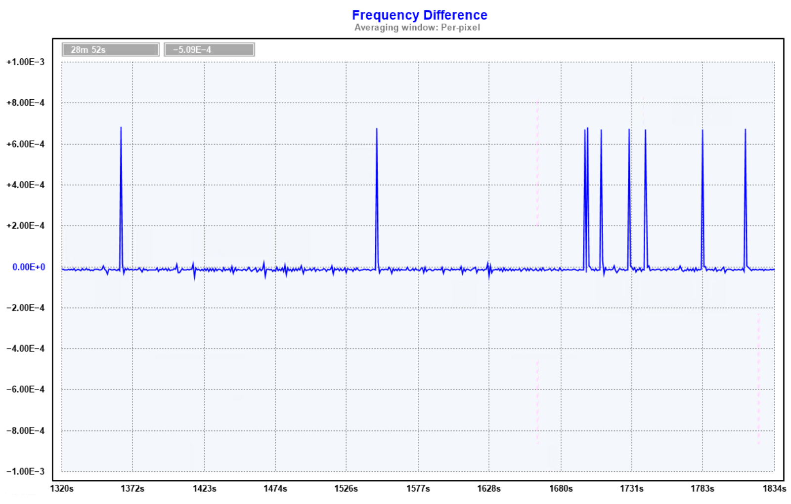
But actually that is _too_ good.
Zooming in shows a persistent 2.75e-5hz offset in frequency

Both the stepping and frequency offset can be clearly seen in the phase difference
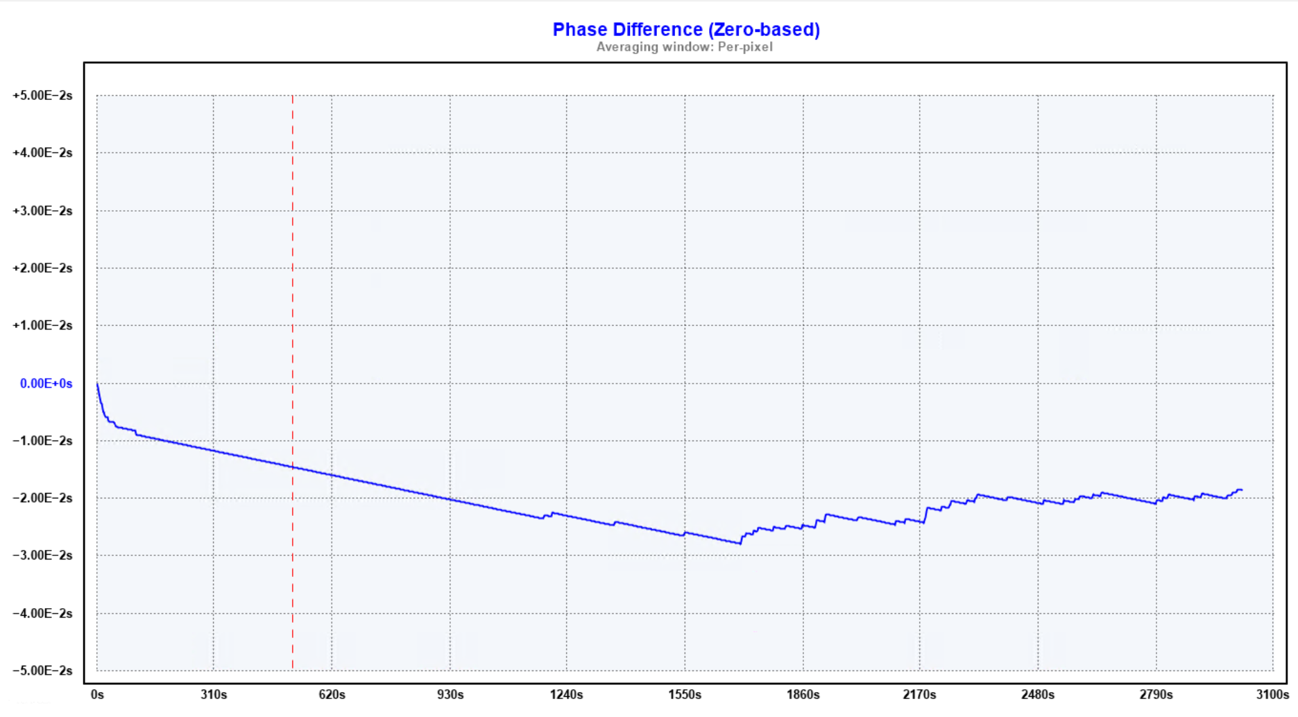
Something is clearly not right.
Discussions
Become a Hackaday.io Member
Create an account to leave a comment. Already have an account? Log In.