 burble
The second prototype has some issues:
- There is a persistent frequency offset and the PID is unable to zero the frequency difference
- The frequency is way too flat and doesn't show any of the expected noise, there are also strange phase jumps where the frequency should be smoothly varying
There could be at least three possible causes for the errors:
- a measurement error
- a software problem preventing the PID from operating correctly
- a physical problem with the circuit or layout
Measurement Errors
I'm very lucky to own a TAPR TICC:
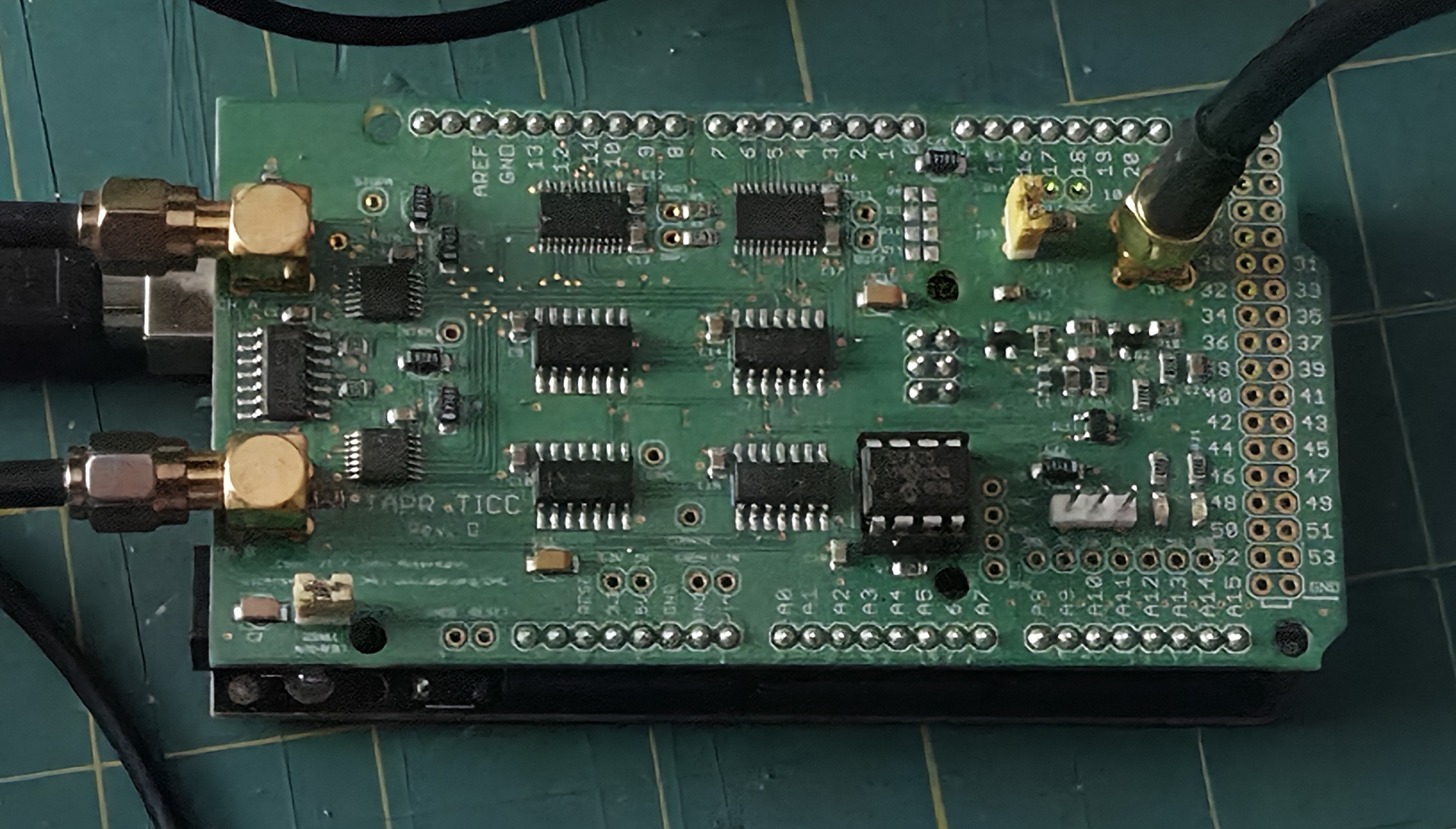
The TICC is a timestamping counter with a very high resolution (~60 picoseconds) and very low noise floor around 1e-10); it's designed to perform long running measurements of low frequency (PPS like) signals so is ideally suited to measure the 1hz output from the 555.
Using the TICC to graph GPS sawtooth errors:
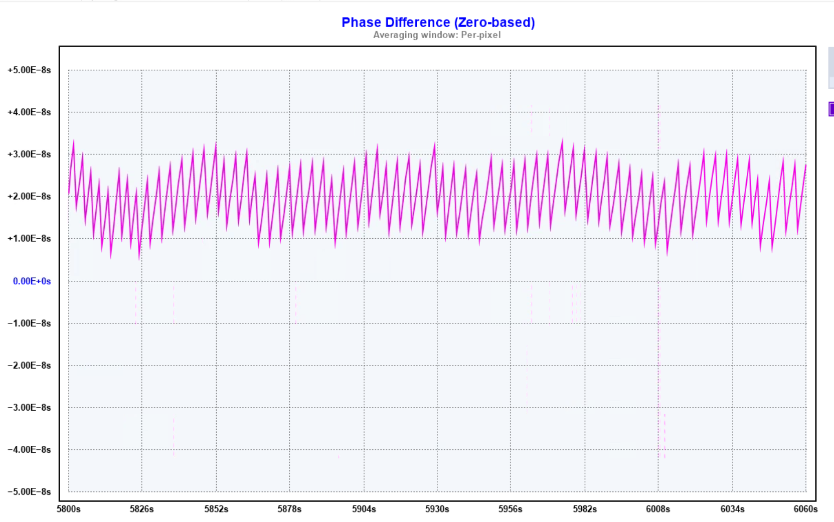 The TICC requires a 10mhz reference clock and has two timestamping channels. By using a GPSDO reference and providing the GPS PPS and 555 PPS on each channel a three cornered hat measurement can be performed to compare noise across the three sources.
The TICC, GPSDO and a standard GPS PPS all have much greater stability than the 555 RC oscilltor by some margin (~4 or 5 decades, at least) so there should be good confidence that the 555 measurements are accurate and the problems seen do not lie here.
Software or Hardware Problem ?
To try and rule out problems with the PID software a simple test was created to sweep the PWM control voltage over a small range between 32768 (the centre frequency) and 33768 . The idea is to check the PWM is being generated correctly and the 555 is responding to the control voltage changes as expected.
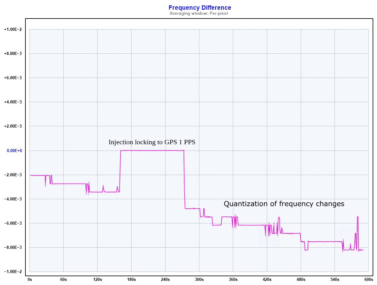
Ooops, that's not right, not at all.
Two separate problems become apparent:
- During the test the 555 PPS became roughly phase aligned with the PPS from the GPS signal and became injection locked. For a small period both signals are locked in sync and beat together exactly
- Rather than smoothly varying with control voltage, the 555 frequency is being quantized in to step changes
Checking how far apart the quantization steps are reveals the culprit; each step is a difference of ~6E-4 which looks suspiciously like 65536 / 100,000,000. The smoking gun is pointing firmly at the use of PWM.
No Surprises
The control voltage for the 555 is very sensitive, with the each step of the PWM corresponding to just 3uV; any slight noise leaking through to the control voltage is going to influence the system.
Conversely, a plug in breadboard is not a low noise environment and creating the prototype with digital components sat together with the sensitive analogue components is asking for trouble. It was inevitable that the prototype would get problems somewhere, so it was interesting to see where this would manifest.
Next Steps
To improve the results we'll need a lower noise build:
- The analogue and digital parts of the system need to be kept apart. Physically, with separate builds and electrically by separating the ground and power networks as much as is possible
- The analogue portion needs to use low noise build techniques with a solid ground plane, no more breadboarding
- The PWM filter needs beefing up to prevent the PWM signal leaking through to the control voltage
- Bypass capacitors, _everywhere_
Spoiler Alert from the Future
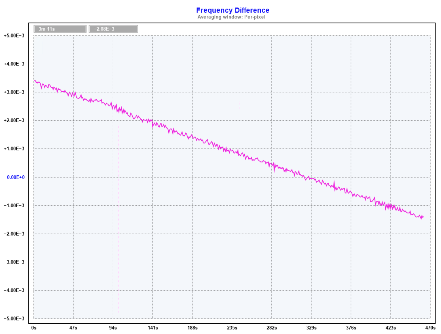
Here's what a PWM sweep looks like in the final build.
The difference is clear, showing the 555 frequency smoothly varying with control voltage and that the PWM control steps are smaller than the inherent noise of the 555 RC oscillator.
 Another Spoiler Alert from the Further Future
A typical GPSDO will incorporate sawtooth correction to improve accuracy and reduce averaging times. This is not going to be required for the 555 as it performs way worse than the GPS PPS, even without taking sawtooth in to account.
Discussions
Become a Hackaday.io Member
Create an account to leave a comment. Already have an account? Log In.