 burble
After seeing noise related problems in the breadboard prototype it's time to get a bit more serious about the build and break out the soldering iron.
The right answer here would probably be to design out a PCB with SMD components and get one of the Chinese fabs to build and ship it. But I'm impatient and I think this breaks constraint (3); a custom PCB is not something I have to hand and it's not cheap and cheerful.
The lowest noise way I know to construct circuits is a deadbug / manhattan style build so that's where we are going. It will look like a pile of junk but will hopefully be enough to get the noise floor down to somewhere 'reasonable'.
Refining the PWM FIlter
Part way through the build, testing out the PWM filter and with the old breadboard prototype still in situ.
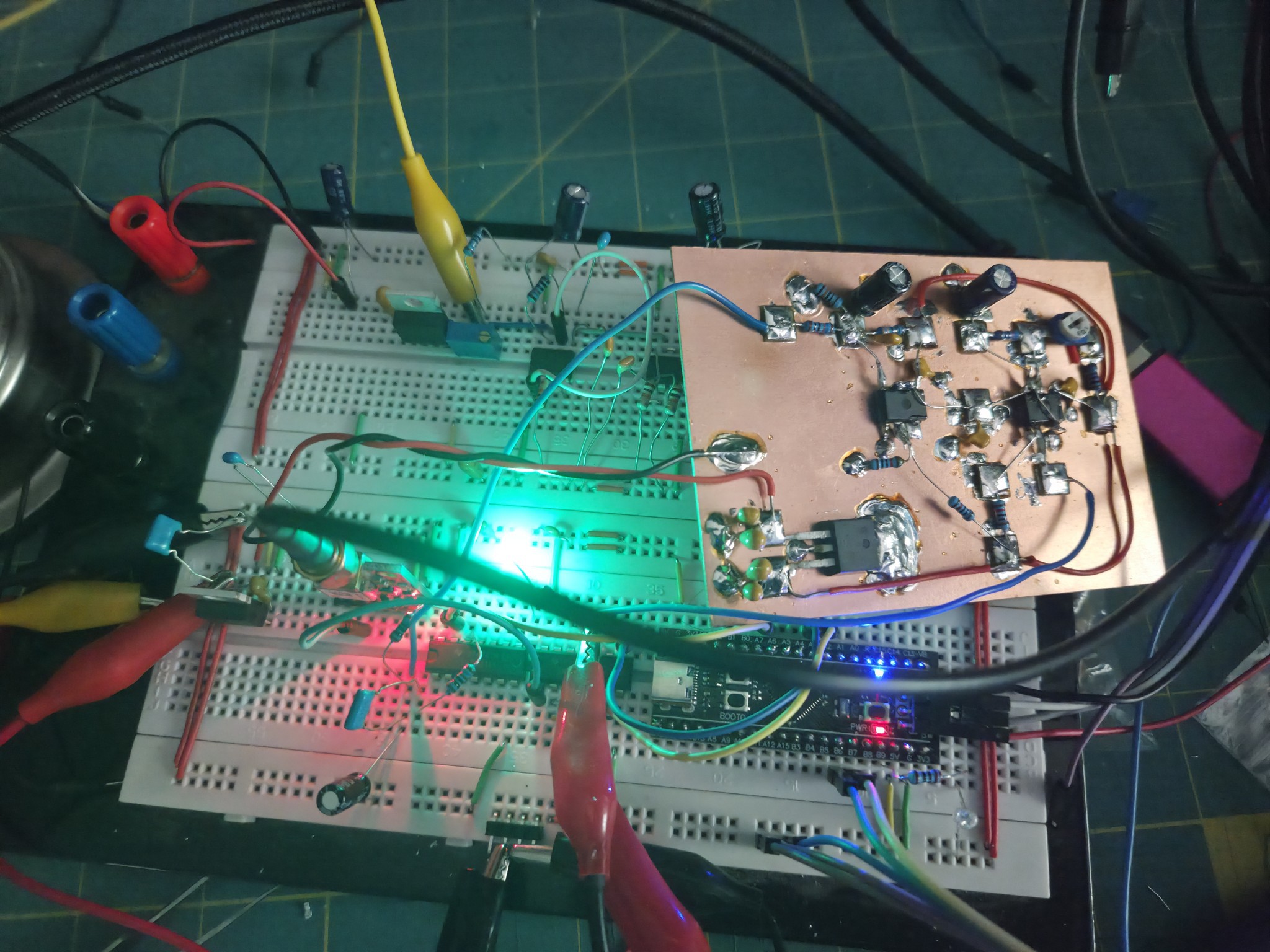
A key objective for the build is to improve the PWM filter and prevent leakage of the PWM signal through to the control voltage. The filter must effectively squash the 1.4khz PWM signal (moooaaar filtering) whilst also remaining responsive to control changes so that the PID functions (but not too much filtering).
This design note from TI provides some inspiration on effective PWM filtering: Designing high-performance PWM DACs for field transmitters
Handily, stm32 MCU have an 'Advanced Timer' peripheral that can generate complementary PWM outputs. These can be used as described in the 'Active ripple suppression' section (page 4) to create a first stage filter with the addition of just a few more passive components.
The PWM filter now looks like this
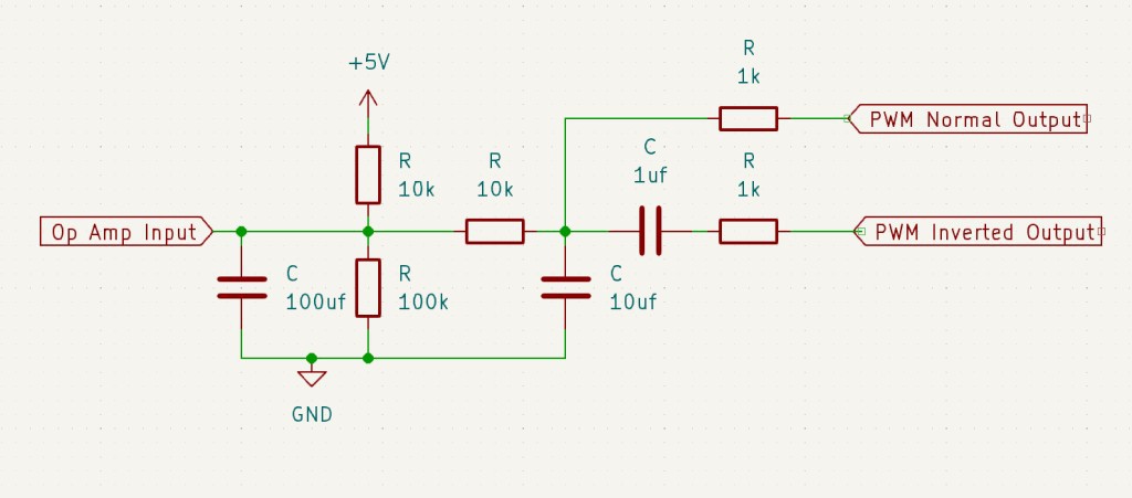
In this configuration the filter is able to move the control voltage between 3.84v and 4.48v with approximately 9uV resolution.
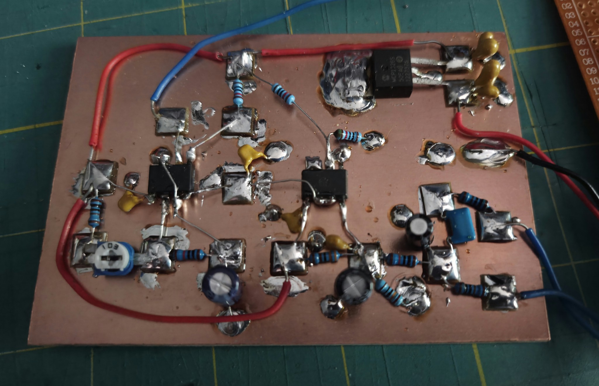
Final Board
Here's the built board in all its janky goodness, complete with excessive amount of bypass filters and solder.
Discussions
Become a Hackaday.io Member
Create an account to leave a comment. Already have an account? Log In.