 burble
Time to see how well the boards perform against, well, time.
In another case of over doing it, here's the measurement set up.
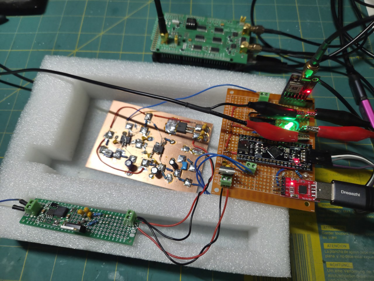
The analogue board is placed in a foam box to protect against drafts that might cause short term temperature variations (Longer term temperature changes should be managed automatically by the control loop).
Frequency and Phase Lock
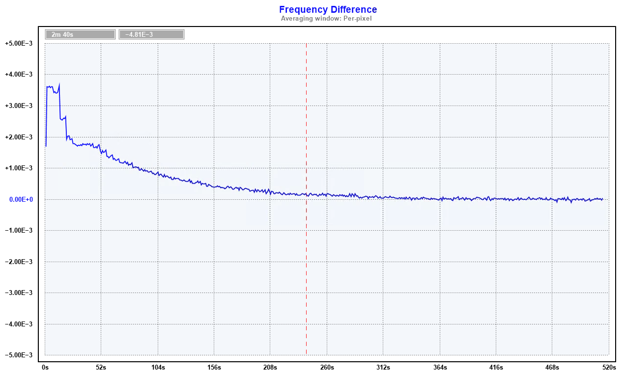
The following graphs show the frequency and phase difference of the 555 PPS against the GPS PPS following a reset.
Frequency offset
Phase offset

The control loop is slow, but this is a design choice and we are in no hurry.
The two PIDs are successfully able to bring both the frequency and phase in to alignment with the GPS PPS.
Here's the view from the MCU parameters.
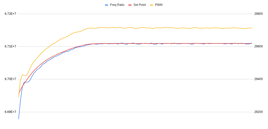
The graph shows the frequency PID maintaining the blue line (measured frequency) against the red line (the frequency set point).
The curve of the red line (frequency set point) shows the phase PID adjusting the set point to drift the phase into phase lock.
Once locked, the phase is maintained with +/- 1 adjustments to the PWM. This hints that there may be slightly better performance available with smaller PWM steps and more control voltage resolution. The board under test has approximately 9uV per PWM step control voltage resolution.
Discussions
Become a Hackaday.io Member
Create an account to leave a comment. Already have an account? Log In.