 burble
To measure the performance of the 555 oscillator we will primarily be looking at the Allan Deviation or 'ADEV'. Oscillator stability is a complex topic and there are much smarter people than me who can explain why ADEV is the measure of choice.
Establishing a Baseline
The first thing to do is capture the ADEV of the 555 RC oscillator when it is unlocked and not being controlled. This represents the base performance that we are looking to change via locking with GPS.

The 555 shows a 'U' shape that is very typical of nearly all oscillators.
The ADEV tells us that, on average, the 555 is counting every second with a variance of just 2.77E-5 (or 27 us).
It can do better though, if we measured the ticks over a 30 second period we can achieve a variance 7.19E-6. This is due to the averaging out of noise sources and is represented in the graph as the bottom of the 'U' shape.
However, if we measure over a longer period it actually gets worse and the variation starts to increase again. This is due to other noise sources, such as oscillator drift, becoming dominant. This is the right part of the graph.
GPS is Different
The PPS from a GPS receiver does not exhibit the same U shape as seen with an oscillator

It's actually just a straight line going down (ignoring a little wobble at the 4-5 second mark that is due to sawtooth).
The atomic clocks in GPS satellites are incredibly precise and any long term noise or drift with the clocks is corrected out. We can take the PPS output from a GPS receiver and look at it over longer and longer intervals and get increasingly lower variance, forever (or at least whilst GPS remains operational).
GPS Disciplining the 555
The aim of GPS disciplining an oscillator is to transfer that long term stability of the GPS signal to the oscillator, correcting the longer term noise sources that are present in the right hand side of the 'U' shape.
Here's how it did:
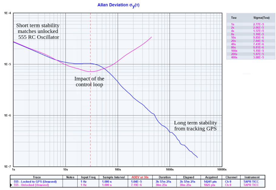
At short intervals, the stability matches that of the unlocked 555 RC oscillator.
The PIDs in the MCU have a maximum averaging window of 18 seconds (16 seconds average and a 2 second settling time after any change). Clearly visible in the ADEV results is a small degradation in the performance as the PIDs adjust the control voltage to lock to the GPS signal. This is the gap between unlocked (pink) and locked (blue) lines.
- The unlocked ADEV shows that the minimum variance in RC oscillator is seen around intervals of 30 seconds. By extending the average time of the PID loops from 16 seconds to 30 we may be able to slightly improve the performance
At longer intervals the control loop is tracking the GPS PPS. The upturn in the 'U' seen in the unlocked oscillator is avoided and the variance continues to decrease with tau in a nice straight line.
Sucess !
The project succeeded at locking the 555 timer to GPS and achieving long term stability.
How Does it Compare to Other GPSDO ?
Badly.
This image shows the typical ADEV of various oscillators locked to GPS, it's borrowed from the SRS website.

Oscillators tend to have excellent short term performance, but poor long performance. On the other hand GPS has poor short term performance and excellent long term performance. The aim of a GPSDO is take an oscillator that performs better than GPS in the short term and get the best of both worlds, fusing the short term and long term performance.
The 555 RC Oscillator does not perform better than the GPS PPS
It's worse, a lot worse, in fact by locking the GPS to a 555 we're actually degrading the GPS PPS signal
It's not even close.
- The one second pulse from the 555 has a deviation of 2.77E-5 meaning it wobbles around, on average, by 27us.
- A standard GPS module has a deviation of around 4E-8 (GPS modules are often spec'ed to 42ns), which is 3 decades or approximately a thousand times better
- A good OCXO or Rb standard will have a deviation under 1E-11, yet another 3 decades down and making them a million times better than the 555
Discussions
Become a Hackaday.io Member
Create an account to leave a comment. Already have an account? Log In.