 The Baiko
- Soldering required
- AVR programming required
Program
This project uses the TinySnore library. The program was uploaded using Arduino as ISP.
#include <tinysnore.h> // Low power library; not needed (avr/sleep.h), but makes it simpler const byte ledsPin = 1; // Low If LED-resistor combination allows to stay well under the 20mA output limit const byte beaconPin = 0; const byte ldrpwrPin = 2; // Pin to 'power up' the LDR only while we read the voltage const byte ldrdataPin = 3; // Voltage read void setup() { pinMode(ledsPin, OUTPUT); pinMode(ldrpwrPin, OUTPUT); pinMode(beaconPin, OUTPUT); pinMode (4, INPUT_PULLUP); // Save some power, probably redundant } void loop() { digitalWrite(ldrpwrPin, HIGH); // Power up the LDR delay(5); // Stabilize int sensorValue = analogRead(ldrdataPin); // Read LDR at voltage divider digitalWrite(ldrpwrPin, LOW); // Power down LDR if (sensorValue <= 300) { // Modify value to make it more or less sensitive to light (0-1023) digitalWrite(beaconPin, HIGH); digitalWrite(ledsPin, HIGH); delay(15); // The beacon is flashing digitalWrite(beaconPin, LOW); snore(1000); // Go to sleep with the position lights ON; change value to } // change flashing interval else { digitalWrite(ledsPin, LOW); snore(3000); // Go to sleep with the position lights OFF; increase } // value to save power but it'll be less reactive delay(10); }
Preparation
- Program the ATtiny85, I used Arduino as ISP.
- Print the circuit guide, place it beneath the glass and replicate it over the glass with thin copper tape. If the adhesive side is non-conductive, solder the tape joints. Use flux and low temperature or you’ll burn the tape.
- Use the schematic and footprint diagram as a guide to place and solder the components. Start with the pin headers (bend them inwards a little with pliers to give them enough tension to hold the coin cell) and work your way out to the edges.
Project background:
This month I finally jumped into PCB design after spending a few months yelling at a few stalled projects that require a working boost regulator circuit. I designed PCBs for a few of my circuits, breakout boards to make my life easier with SMD ATtiny85, and a bunch of 'test regulator' boards to see if I can finally leave behind this era of despair and LCR parasitics (and probably enter an even worse era of more complex problems).
It turns out PCBs take a while to arrive so the idea came to design a 'single layer' board and recreate it with copper tape. I made the design as visually appealing as I could. You can probably make it look cleaner if you use the kind of tape that is conductive on both sides, so you don't have to solder the joints. I was also tempted to use the surface mount version of the MCU, as I've made different projects by soldering coil wire to its tiny legs, but decided to 'make it pop' (hopefully only figuratively) with the TH version.

 M.R. Inc
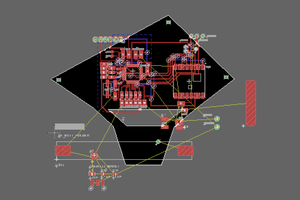
 Sophi Kravitz
 hesam.moshiri
 Sagar 001