 Peter
PeterFor more details about the complete project, including a project log with more than 100 log entries, see my relay CPU project:
Homepage of the relay CPU project
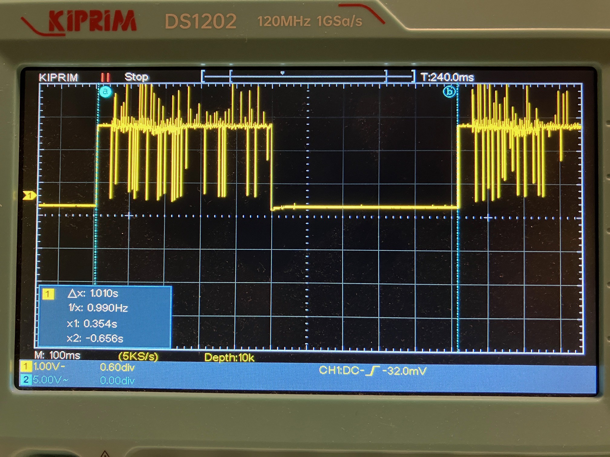
This video, supported by further details in the log section, serves as my entry for the 1 Hertz Challenge.
And below are some technical details about the system.
The following picture shows you an overview about the complete system.

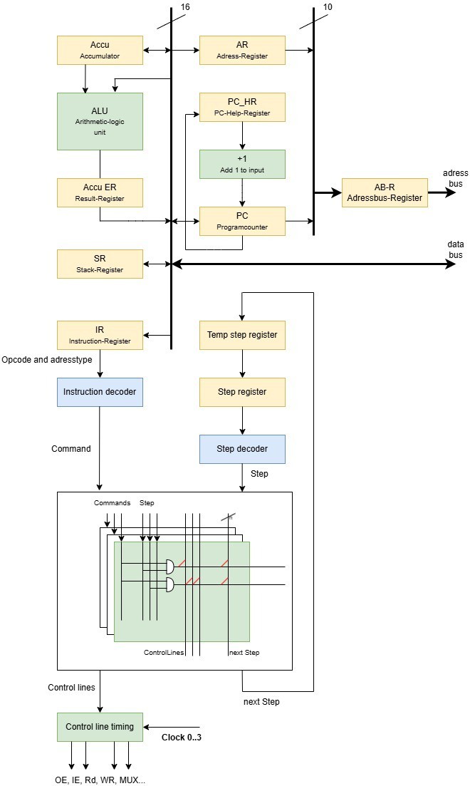
The following diagram shows the logical structure of the 16 bit relay CPU. It was built around an accumulator. A special feature is that the program counter has its own +1 adder. There is also a register that can store a return address, enabling one level of subroutine support.
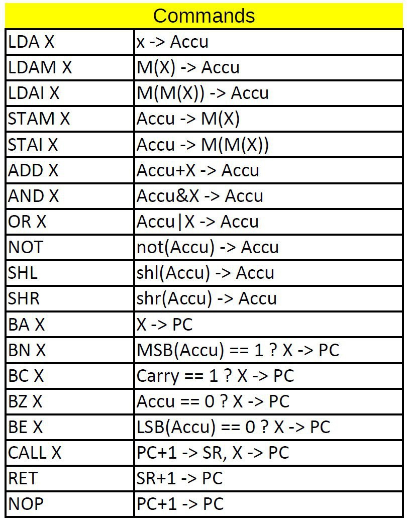
The command set of the CPU:
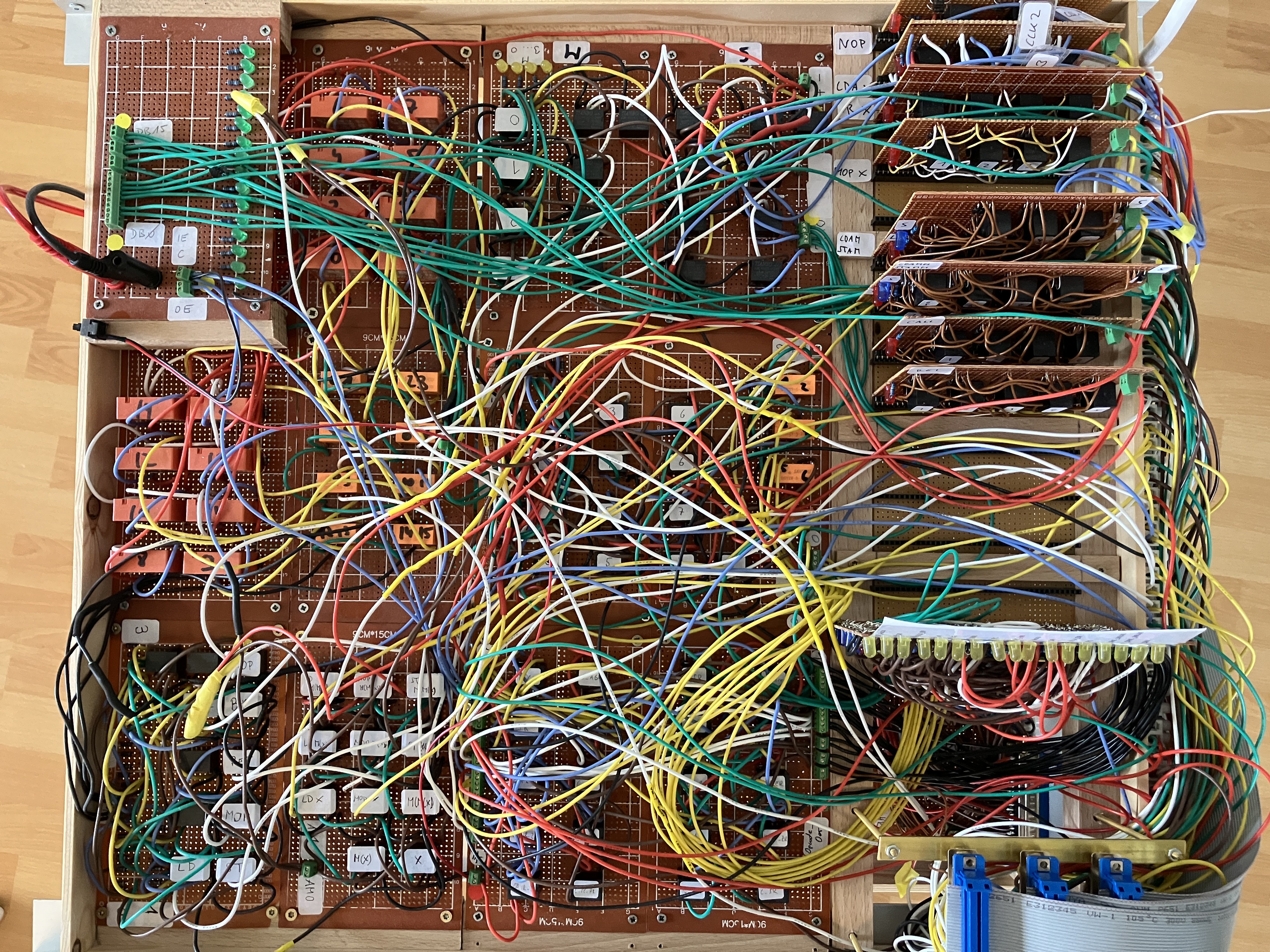
And now you see some pictures of the different module boards. The first one here is the control board:
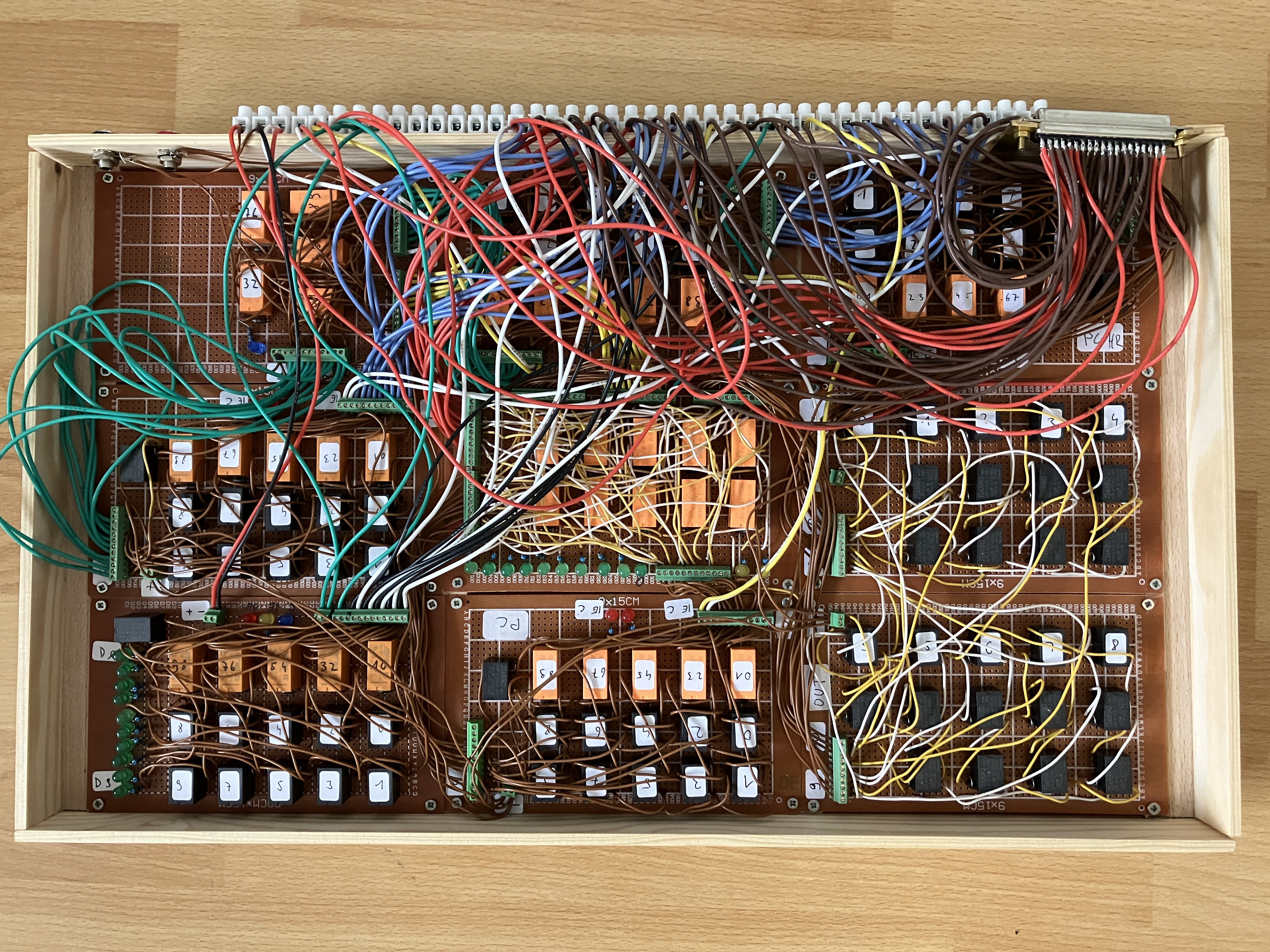
The following board is responsible for address calculation:
Here you can see the complete ALU, the accumulator register, and the branch logic. The green PCBs make up the 16-bit ALU, while the small boards at the bottom implement both the branch and carry logic.
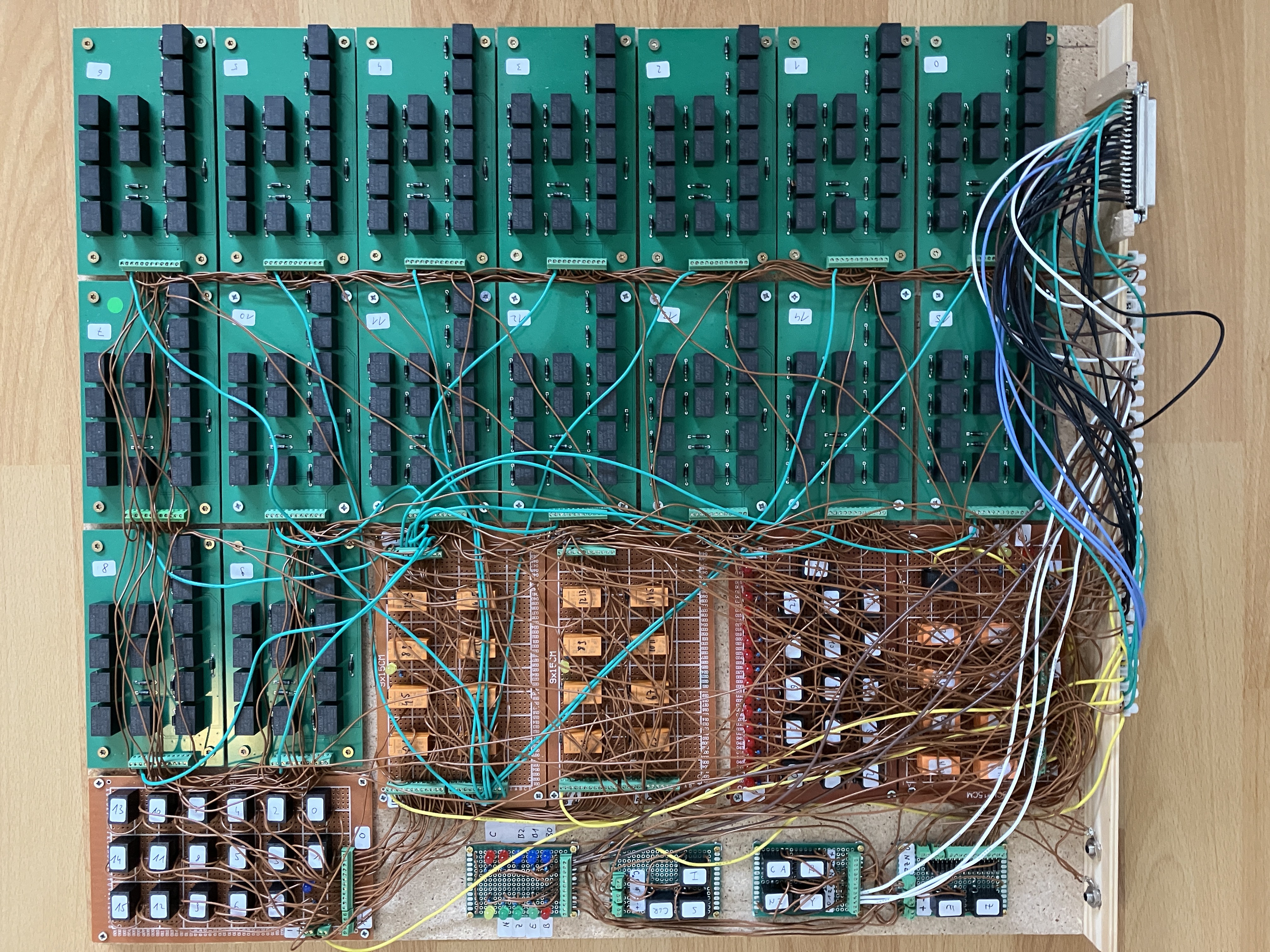
Here is the input/output decoder, the 16-bit output register, and the contactor, which switches the lamp.
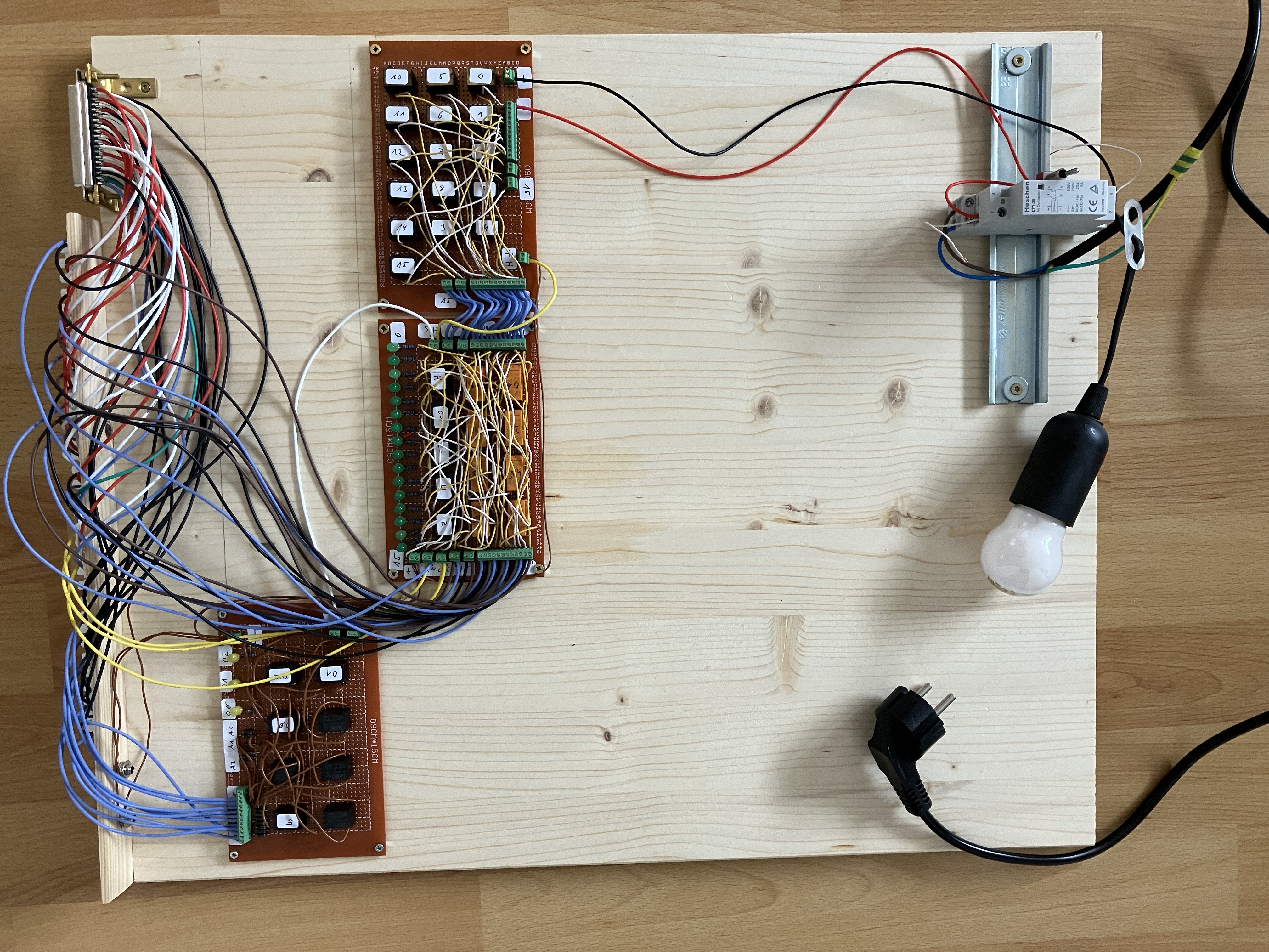
At the very bottom, we find the memory implemented using an Arduino, as well as the clock generator, which is also built with a separate Arduino.


 Augusto Baffa
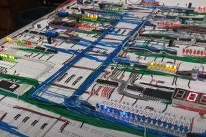
 Fábio Gil
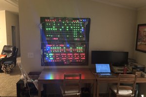
 spudfishScott
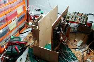
 zaphod
Love it! I presume you didn't create the whole CPU just for the 1Hz challenge.