 Zachary Murtishi
I tend to use a lot of CR2032 coin cells in my designs and they are pretty pricy as a single-use item. I figured I would attempt to make use of ML2032 cells where possible. The ML2032 is a lithium manganese dioxide battery that can be recharged, unlike CR2032 cells.
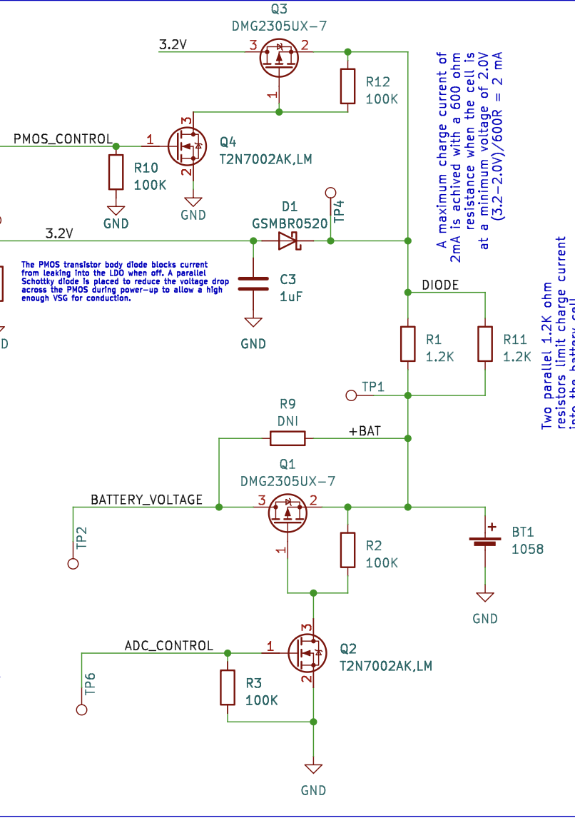
The ML2032 manufacturers recommend the use of a constant-voltage charging circuit making use of a linear regulator, diode, and current-limiting resistor. The linear regulator is selected for an output voltage of 3.2V, ensuring that it is not possible to charge to the absolute maximum voltage of 3.3V. The diode is placed in series to prevent reverse current from flowing from the battery cell to the linear regulator output. The current-limiting resistor is sized to limit the charge current to a maximum of 2 mA when the cell is at a minimum voltage of 2V. I've decided to design my own circuit based around this concept, but with some changes.
Here, a TPS73132DBVR LDO regulator was used to generate a 3.2V output from a +5VDC Micro USB input. Two 1.2K ohm resistors in parallel were used to set a 600 ohm resistance for charging; in theory, this will limit the charge current to 2mA for a minimum battery voltage of 2.0V and charge voltage of 3.2V. The minimum battery voltage specified by ML2032 manufacturers sits at around 2.0V - as a result, this charger will not charge batteries below that cutoff.

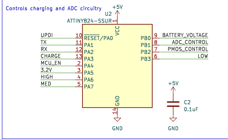
The first change is the addition of an ATtiny824 microcontroller. The ATtiny 2-series is great - it has an integrated 12-bit analog-to-digital converter, which allows reasonably accurate measurements for tracking the charge cycle of the cell. As a microcontroller, it can also control the charge cycle through its digital i/O circuitry. Analog-to-digital channels of the ATtiny are connected to the regulator output and battery cell's positive terminal to track the progress of the charge cycle. Due to the fact the microcontroller is powered from a variable +5VDC input, it uses a built-in 4.096V voltage reference for ADC measurements.
I've selected a GSMBR0520 diode as the current-blocking diode here, which has a reasonably low forward voltage (~100mV) in the <10mA current region. This diode is used solely to quickly turn on a DMG2305UX-7 PMOS transistor placed in parallel with it. This PMOS transistor is enabled during charging to short the diode (and its forward drop) to create a low-resistance path between the regulator output and current limiting resistors.
The drain is placed in line with the 3.2V regulator output to take advantage of the body diode and block reverse voltage from the battery from inducing a current flow into the LDO output. The 20V PMOS rating is in line with the 20V Vr rating of the diode, which works for this design. The low Vf GSMBR0520 allows for a 3.2V-0.2V (~3V) voltage to appear on the source of the DMG2305UX-7, which can conduct with a VSG of only 1.8V. A 2N7002 NMOS transistor is driven by the ATtiny microcontroller whenever charging is enabled; the drain is connected to the gate of the DMG2305UX-7 to generate a positive VSG value and drive the transistor.
Similarly, off-state leakage from the battery into the microcontroller is prevented through the use of a discrete PMOS/NMOS pair. A PMOS transistor controls the battery's connection to the ATtiny ADC pin, which is in turn controlled by a microcontroller-activated NMOS transistor. A discrete NMOS transistor is used to avoid current leaking into a microcontroller pin, as a 100K source-to-gate resistor is used for biasing and requires a connection with the gate. To prevent this biasing resistor from reducing the charge current flowing into the battery, this circuit is only driven during ADC reads.
Charging is enabled only when the battery is at a minimum voltage of 1.9V; any lower and the ATtiny will not recognize that a battery has been inserted. The battery will continue to charge until a voltage of 3.1V is detected; at that point, the charge cycle will end and no more curent will flow into the battery. When charging is enabled, the 3.2V regulator is turned on through an ATtiny-controlled enable pin and the PMOS transistor in series with it is set to conduct. When disabled, the output of the 3.2V regulator is disabled and the PMOS transistor is put into the cutoff region by allowing the gate to float high.
A set of LEDs indicate the current state of the battery and charge cycle. These LEDs are controlled by the ATtiny microcontroller using data collected from its analog-to-digital conversions. Three LEDs (green, yellow, and red) are designed to indicate the charge level of the battery. Green indicates a high voltage level (>2.9), yellow indicates a medium level (2.3V - 2.9V) and red indicates a low voltage (1.9V-2.3V); a blinking green LED indicates that the battery is overcharged (>3.2V). Another red LED ("charge") is intended to communicate the charging state to the user; a blinking LED indicates that charging is active, an off LED indicates that charging is complete, and a red LED indicates that the battery is either not present or is overcharged.
A self-test feature runs at startup and ensures that all LEDs can be activated and that the 3.2V regulator is operating with a 3.175V to 3.25V output voltage. The ATtiny824 ADC is used to verify the output voltage of the battery.
The battery is housed in a Keystone 1058 battery holder, where it may be easily removed when it has completed charging.