So for this i use a quad opamp -> LM324DR
Because i have a bunch of them from the 1Hz challenge project.
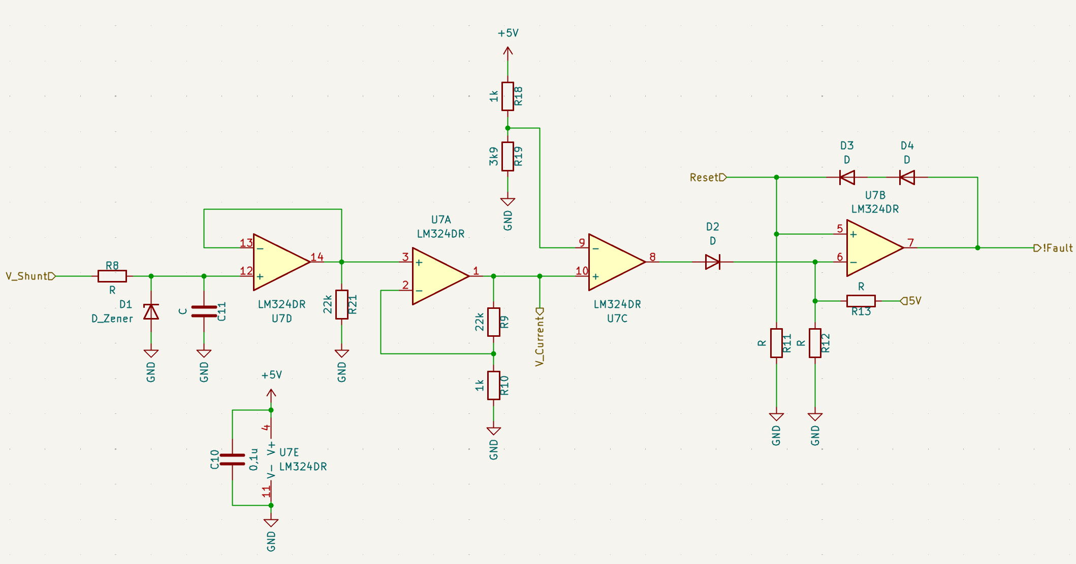
From left to right:
- A zener diode for safety, and a RC-filter. This is useful to filter fast spikes or allow short OC´s .... lets keep the values open for now and see at the first prototype.
Also i decouple the input. - The amplifier. I want to get to a trigger voltage of ~4V
The shunt (which is the weakest link in the chain) is 3W max -> ~17A = 170mV
4V/170mV -> A=23
Using 22k and 1k from the E24 line we get exactly 23 ... convenient - Shutdown trigger. The moment the voltage from the amp is above V-, it triggers.
Unfortunately, getting the reference voltage precicely is not (cheaply) possible. i opted for the 3,98V ... close enough.
So the shutdown threshold is a bit below 17A ... ok - The flipflop .... so you can use a opamp as a RS flipflop ... nice
When the shutdown is high, the flipflop will output a LOW signal ... so a active low fault .....
This can be reset by a high-flank on the reset input ....

This feeds into the Shutdown lane which is just a bunch of AND-gates.
First gate outputs high when the enable and fault is high. The other 3 gates forward the highside signals, but only if the first one is also HIGH.
Fault active or Enable LOW = no signals to the driver = no switching of the high side fet´s = no output power.
Discussions
Become a Hackaday.io Member
Create an account to leave a comment. Already have an account? Log In.