Project Idealization
As a first step, each member thought of at least 2 possible projects to be undertaken. By means of a vote, 1 of them was chosen, and from this point the idealization of the project itself began: Which materials to use, how to program the board to carry out the key functions, etc. For this, a first Diagram of the project was structured for the superficial analysis of the plant.
Initial Diagram
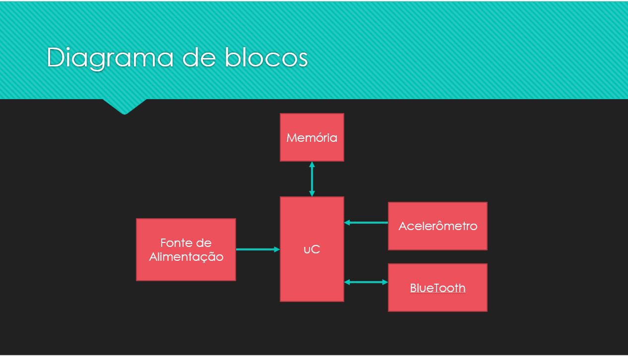
Below: The idealization of the Block Diagram for the project
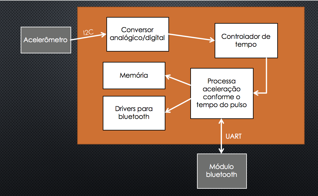
Below: Block Diagram of Bluetooth Device
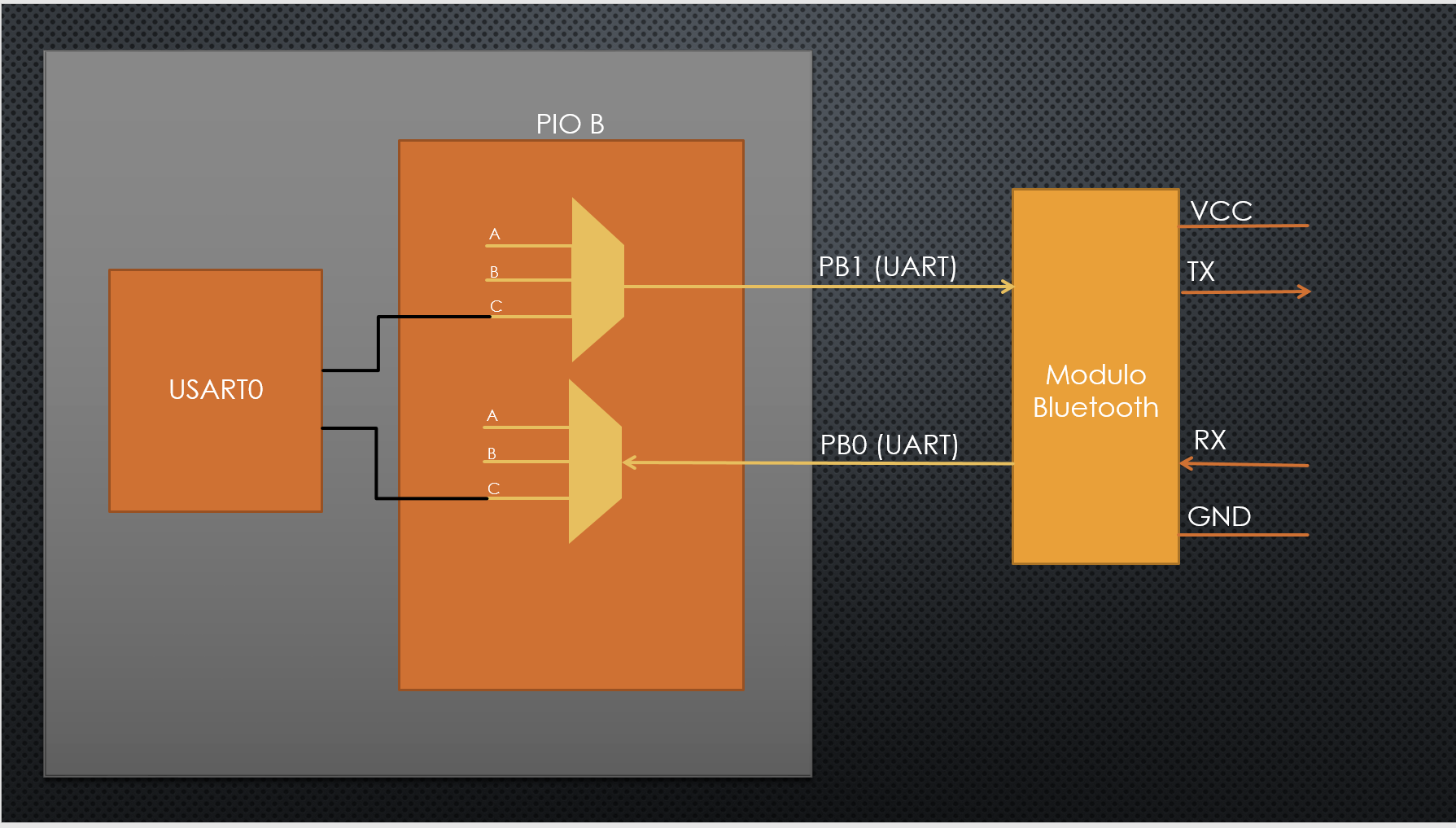
Description of the Diagram
The idea is that the user places the prototype of the counter next to the weight of the machine on which the exercise will be performed. With a prior calibration of the movement to be performed on the repetitions, the counter ensures that all movement will be perfect. Otherwise, repetition will not be considered. The number of repetitions to be executed, as well as the calibration, can be saved in the prototype's own memory. The user can communicate with the counter through an interface still to be thought, probably an application. In this interface, you can tell which machine will be used and the number of repetitions. A machine that has previously been calibrated will not need a new calibration, since this information will already be in the device memory. Finally, the movement will be perceived through an accelerometer coupled to the device.
Accelerometer Measurements Validation
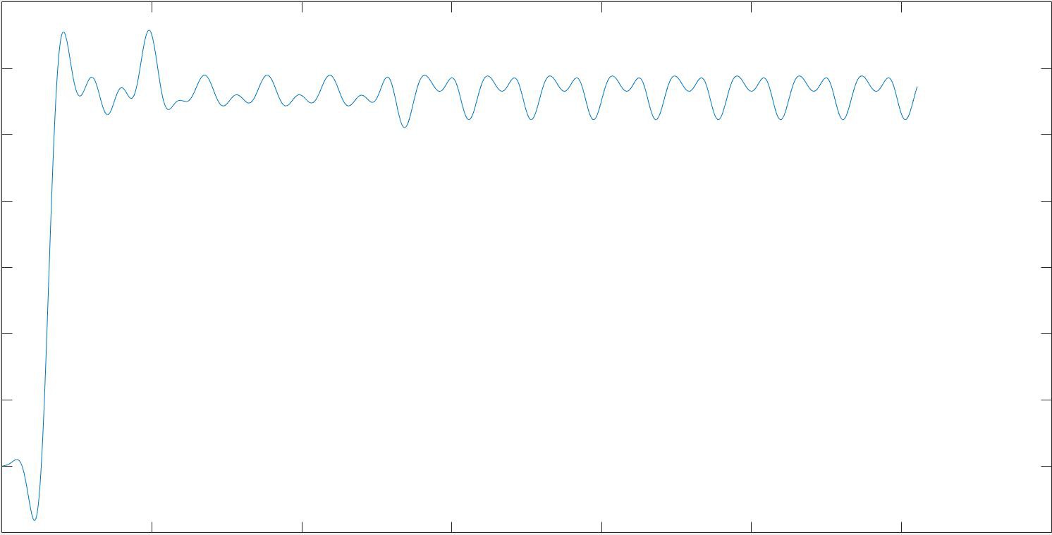
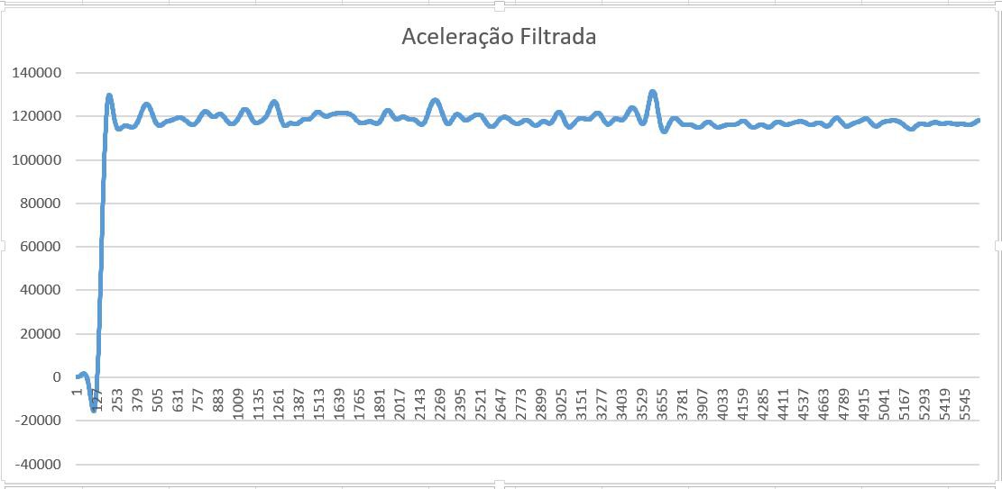
We used Matlab software to create a FIR filter capable to get information from the sensor, and transform all data into numbers that make sense to work with. For example, we had to throw all great variation out, working only with low range of accelerations. Also, we had to calibrate it by making tests, in order to find the error range. Finally, a program using Atmel Studio implements the FIR filter, as can be seen in the images below.
Qualitative graph of a FIR Low Filter implementation using MATLAB
Below, the comparison with the qualitative acceleration graphic made using Atmel Studio software
We can observe that the results are very alike each other, what means that the implementation was successfully done.
Detailed Diagram
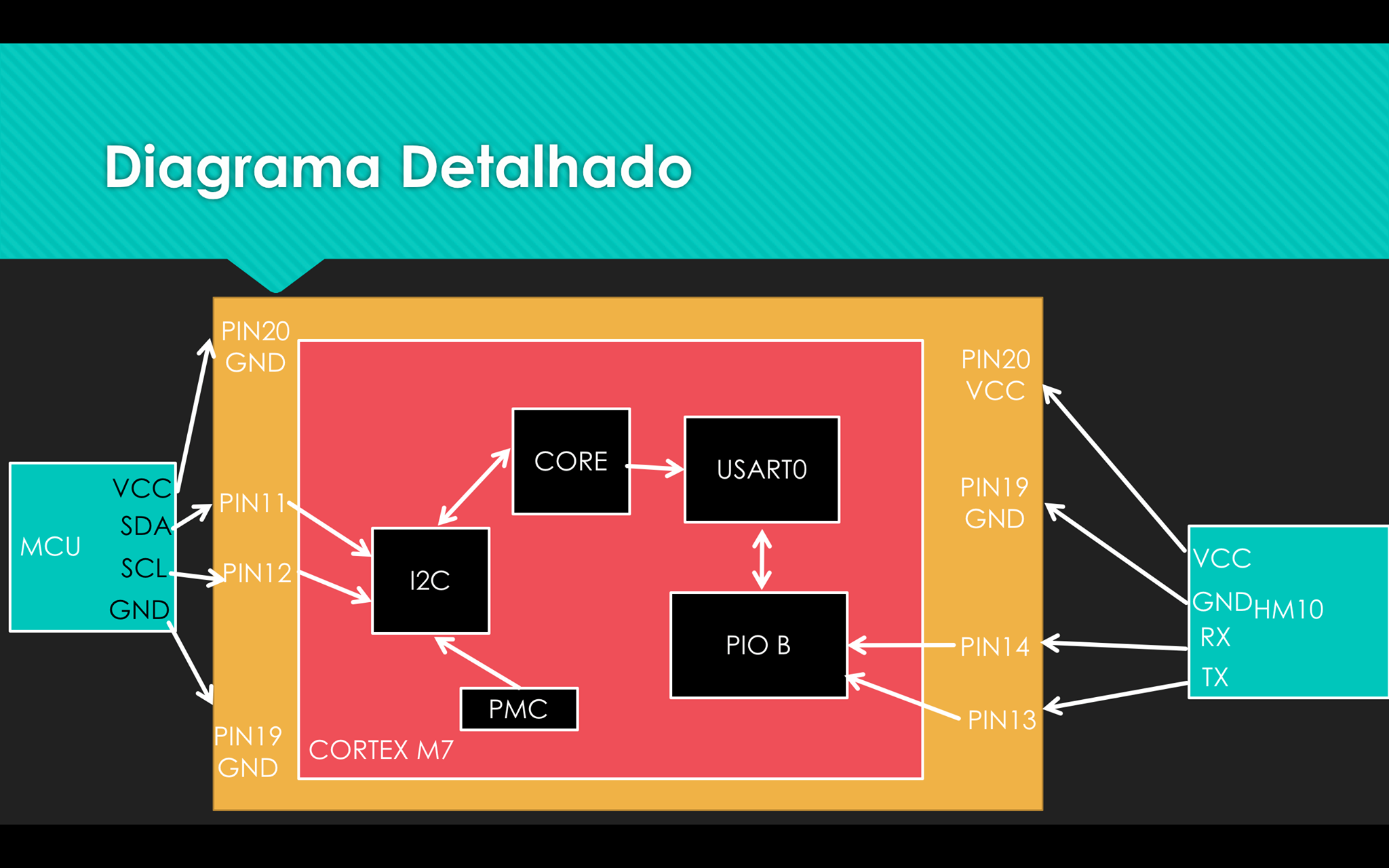
Description of the Diagram: Same-70
This diagram contains all the info that we searched for doing the project. All the pins, peripherals and connections are ilustrated on that image. We can see the bluetooth (HM10) and the accel. (MCU) there too.
 Gabriel do Vale Rios
You really did a great job making this electric program object. I want to embed it with my webpage. You can see this here
https://exercisevela.com/how-to-exercise-for-weight-loss-at-home-for-female