Lithium ION
When it comes to signal processing through a digital medium then DSPs are the one who comes into play. Basically here we are talking about audio signals and music. In the convention audio system there are analog systems consisting of a lot of opamp drives and knobs to adjust the different settings. A basic analog system may perform well but it is bulky and not realizable in certain places where we want a computer control. On the other hand these DSP units are cheap and easy to configure with a microcontroller.
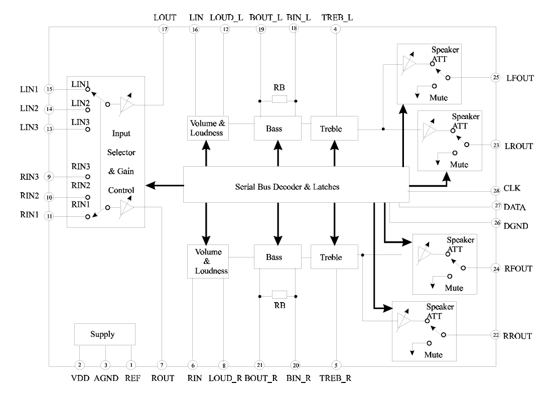
I found the one, it is quite old “PT2313” from Princeton Taiwan. PT2313 is a four-channel digital audio processor utilizing CMOS Technology. Volume, Right/Left Bass and Treble Balance, Front/Rear Fader Processor are incorporated into a single chip. Loudness Function and Selectable Input Gain are also provided to build a highly effective electronic audio processor having the highest performance and reliability with the least external components. All functions are programmable using the Serial Bus. The pin assignments and application circuit are optimized for easy PCB layout and cost saving advantage for audio application.
This PCB is sponsored by PCBWAY. I have ordered the PCBs, because I have been using the services for a long time. PCBWAY is the only well known company which deals in PCB related products. Here you will get fulfilled all the prototyping requirements.
Features of PT2313:
- Least External Components
- Treble and Bass Control
- Loudness Function
- 3 Stereo Inputs with Selectable Input Gain
- Input/Output for External Noise Reduction System/Equalizer
- Controls for Fader and Balance
- Independent Mute Function
- Volume Control in 1.25 dB/step
- Controlled by Serial Bus Micro-Processor Interface
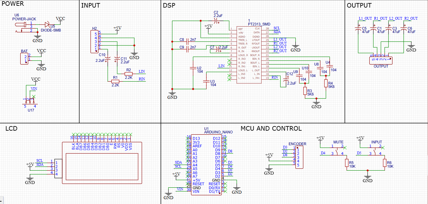
Circuit Diagram:
I am using this chip to feed to an amplifier circuit, this chip can be used as a standalone preamplifier circuit. Now because it has 3 inputs, but here I don’t need that much so I am using only one of them. But at the output I am using all 4, in which 2 will not work (reserved for later). So this will be a 2 channel system through which I can control Channel gain, volume, bass, table and balance. Because the system works with I2C we can directly connect a compatible microcontroller like UNO/NANO. Some required components are:
- PT2313 DSP
- 16X2 LCD with I2C
- 5.6K, 10K, 2K2 Resistor
- 100n, 2.7n, 10u, 47u Capacitor
- Encoder Module
- Arduino Nano
- Tactile Switches
The circuit diagram given here is fully tested and designed to minimize the noise, all the digital section is kept away from the signal conditioning part. To avoid noise issues. This has a 16x2 LCD, an Arduino Nano, an Encoder and some resistor for external configuration.
Code for DSP:

Basically we have pre-made libraries to implement different functions, all of which are designed based on the register information given in the datasheet. For example the one shared below is for a general register map. After programming the register map the location and data is sent through I2C which fills the resistor and changes the output characteristics of the IC. In the next few tutorials we will try to design our own PCBs and libraries but right now using an open source example from the web. Download the datasheet and library from here and code is given below for the same:
// Get the library: https://drive.google.com/file/d/1NmqZHj--yFQHnVIe1FuU4L_6juC5jjzR/view?usp=sharing
// Code shared in the files section download from there
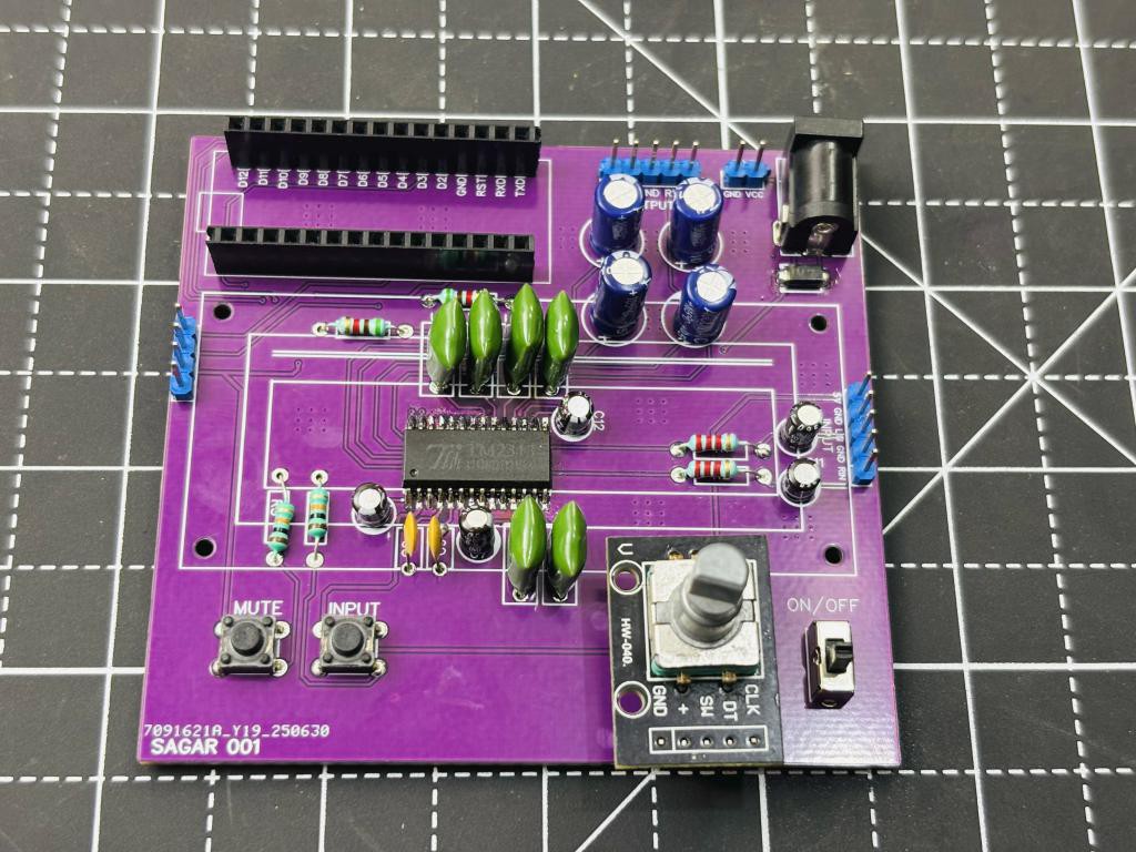
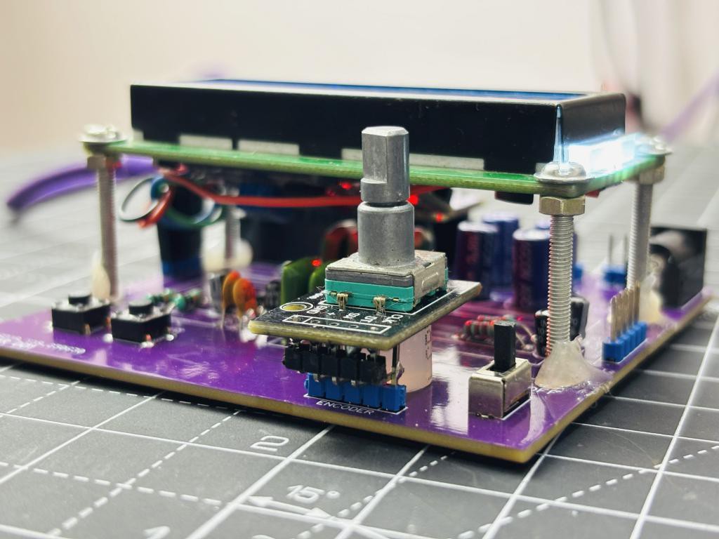
PCB Designs:
I have designed this PCB, in which I considered signal integrity. The PCB is designed to minimize the crosstalk and noise of the signal. I have put the IC in the middle and external components around it. Because here we are using a 16x2 I2C LCD. It is installed with screws at a little height, so all the DSP part is built under that. Moreover we have Arduino NANO on the top of the board and a DC barrel jack on the opposite side.
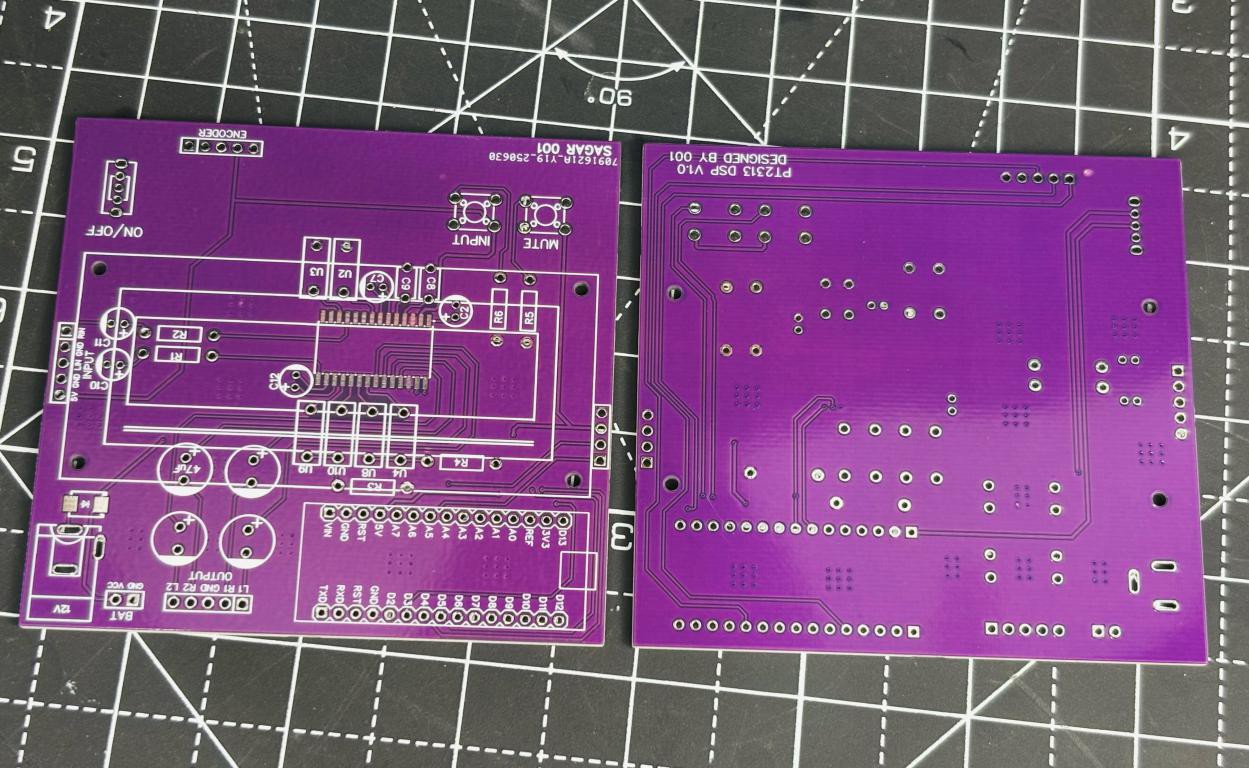
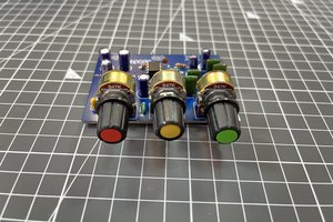
Coming to the control section instead of different potentiometer knobs...
Read more »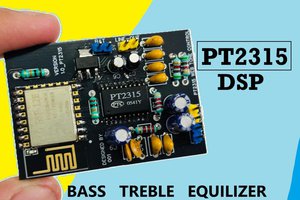
 Sagar 001
 Hiro Akihabara