 Dorian Coves
Measuring small resistances value isn’t new to most engineers — but once you get down to the milli-ohm or micro-ohm range, small details start to dominate. Wiring and connectors can add more resistance than the part itself. Contact resistance can change between measurements. High test currents cause self-heating, altering the value you’re trying to capture. And even tiny temperature differences between metals can generate microvolts that mask your real signal.
The Main Challenges
- Parasitic Resistance Wires, connectors, PCB traces… …all add unwanted resistance.
- Self-Heating High current improves resolution, but even a few °C rise can cause a 1 % error.
- Noise & Resolution Limits Measuring 60 µΩ at 1 A means resolving 60 µV — far beyond the 10-bit ADC of an Arduino UNO.
- Thermoelectric Voltages

The Reliable Fix: 4-Wire Measurement
The only robust method is the Kelvin (4-wire) connection:
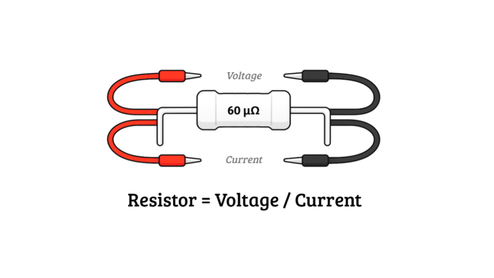
Two wires inject a known current through the resistor. Two separate wires measure the voltage drop.
This bypasses wiring resistance and lets you use a high-impedance voltmeter or precision ADC for clean readings.
Limit heating by applying current only during measurement. Your resolution will depend on voltmeter precision, range, and source current quality.
DIY 4-wire setup
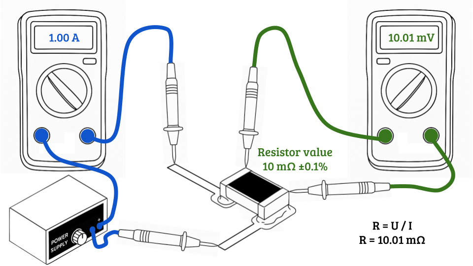
You can try this right now with:
- A power supply
- Two multimeters
- Four probes
One meter measures current, the other measures voltage. Simple, but dramatically more accurate than a 2-wire setup.
Measuring micro-ohms isn’t magic — it’s about eliminating every source of error.
In the next log, I’ll share the open-source design that inspired me to build my own compact, “low cost”, precision micro-ohmmeter.
Discussions
Become a Hackaday.io Member
Create an account to leave a comment. Already have an account? Log In.