 Dorian Coves
Before designing my own precision micro-ohmmeter, I started by studying an excellent open-source project by Dennis Vollrath, published in Servo Magazine:
https://www.servomagazine.com/magazine/article/build-a-simple-micro-ohmmeter
It’s a compact, well-thought-out DIY design with solid explanations — a perfect starting point for anyone exploring low-resistance measurements.
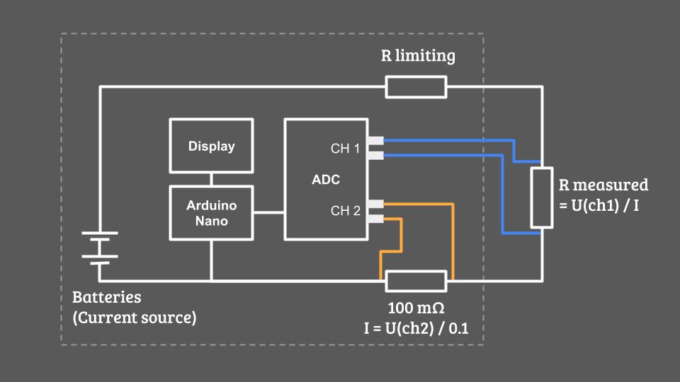
Simplified schematic of Dennis Vollrath’s design
What Makes Dennis’ Design Great
This project achieves surprisingly high performance for something you can build at home thank's to:
- High test current — around 1.2 A
- 18-bit ADC ENoB ! (17 bits in unipolar mode)
- Programmable differential amplifier with gain up to ×8 (in the ADC)
That translates into an estimated measurement resolution of:
Resolution = ADC voltage step / Current = (0.256 / 2^17) / 1.2 = 1.6 µOhm
For a device you can build for under €50, that’s remarkably good — especially with such a short BOM and a straightforward assembly.
Why I Had to Go Further
While Dennis’s design is excellent for hobbyists, my goal was to build something industrial-grade for integration into automated test benches. That required several key changes:
1. Professional Hardware
I redesigned the PCB to meet professional manufacturing standards — compact, robust, and ready to fit inside a proper enclosure with DIN rail mounting and standard connectors.
2. Power Supply Upgrade
The original design used batteries and a 5 Ω resistor to limit the current (Power loss = R*I² = 7,2 W in heat). My version had to work directly from the client’s 24 V DC supply, so I redesigned the power stage to efficiently deliver a stable, high test current. I also added circuitry to pulse the current only during measurements to avoid unnecessary heating.
3. USB-Only Interface
Since the device is part of an automated test bench, it doesn’t need a screen. I switched to a USB-only interface and rewrote the firmware accordingly to communicate directly with the client’s software.
4. Improved Analog Front-End
I added analog filtering on the ADC inputs and carefully optimized the PCB layout to minimize crosstalk and noise pickup — critical when you’re measuring signals in the microvolt range.
5. Calibration for Accuracy
Finally, I wanted each unit to be factory-calibrated against precision reference resistors to guarantee performance and reproducibility. I’ll share more about the calibration process in an upcoming log.
What’s Next
Dennis Vollrath’s project was a fantastic foundation, and my version takes the concept further — from a DIY project to a precision lab instrument.
In the next log, I’ll unveil my custom micro-ohmmeter design — optimized for accuracy, reliability, and industrial integration.
Stay tuned!
Discussions
Become a Hackaday.io Member
Create an account to leave a comment. Already have an account? Log In.