 bi0sbootmedia
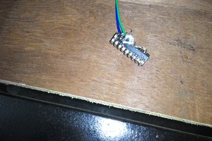
A USB 2 + Battery Conversion Mod easily applicable to any modern android phone!
0%
0%
PhoneBlox
A Old Phone Concept Brought Back To Open-Source Life!
Become a Hackaday.io member
Already have an account? Log in.
Just one more thing
To make the experience fit your profile, pick a username and tell us what interests you.
Pick an awesome username
hackaday.io/
Your profile's URL: hackaday.io/username. Max 25 alphanumeric characters.
Pick a few interests
Projects that share your interests
People that share your interests


 Srinivas Nistala
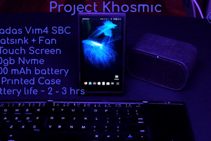
 Conceptual Hardware
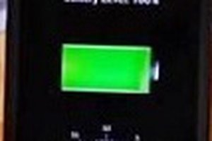
 Ahmed Bilal
 Badar Jahangir Kayani