Rudra Lad
Continuation of a recent project
A couple of months back, I published a project on hackster.io (and source code on github) which involved a great level of manual size optimizations to create a blinky for STM32F4 discovery board with compiled binary less than 50 bytes in size. This work is highly inspired from 100 Bytes Blinky Challenge on Segger Blog.
It is recommended to refer both of these before continuing further. Description below extends the same project to reach much closer to 1Hz, while still keeping the size less than 50 bytes as before.
Summary of optimizations carried out so far
It is strongly recommended to refer to the hackster blog port, however below is the list of optimizations carried out till delay_blinky_09 example in github repo :
- Not using the startup code, instead writing application directly in Reset_Handler. Omitting the startup code restricts the variables to stack memory (local variables) only, because there is no startup code to perform copy of .data section and initialize .bss sections.
- Not using stack memory and storing the local variables in arm cortex m4 core's general purpose registers. This limits the number of variables up to the available general purpose registers. This is achieved by declaring local variables with register keyword.
- Using Bit-Band for peripheral register read/write/modify. Normal read-modify-write way requires more instructions to perform atomic write operations on individual bits of any peripheral register.
- Declaring Reset_Handler as naked function, so that function prologue/epilogue are not generated by compiler. This is fine because we are not calling any functions or performing any stack operations.
- Removal of initial stack pointer from vector table (since we are not using stack) and starting it directly from the reset vector. It requires vector table to be loaded with offset of 4 bytes to cater the missing initial stack pointer.
- Caching address of GPIO IDR (Input Data Register) and GPIO ODR (Output Data Register) to general purpose registers, so that same address is not read from ROM each time a write is done to ODR. This can be considered a speed optimization and not specifically a size optimization.
- Using Bitband allows to use NOT (mvns) instruction to toggle a bit in ODR, instead of using XOR (eor) instruction which takes 2 bytes more.
- Reusing the same register variable for different writes to different peripheral registers during initialization.
- Preferring instruction which use immediate load instead of load from a ROM location. This constrains the values to be loaded to few significant digits only, or else will result in load from ROM location instead of immediate load.
The delay required for toggling LED at 1Hz is achieved using blocking software delay, which involves counting to certain number for spending (wasting) given delay time. Therefore, with implementation of each new optimization, the code execution time changes based on the instructions generated by compiler. Hence, it requires tuning the delay value by trial and error so that resultant blink frequency is closer to 1Hz.
Where do we stand, how much closer to 1 Hz ?
delay_blinky_09 uses a delay value of 2097152 (2^21 or say 1<<21) to be compared against counter for toggling the LED. This value was chosen as it is a natural power of 2 and hence allows immediate load instruction to keep size below 50 bytes. Below is the waveform at Red LED (PD14) for this example (taken using 24MHz logic analyzer).
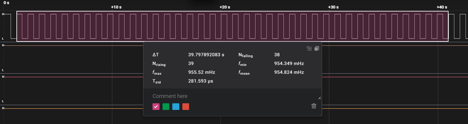 Hence, with reference to logic analyzer's 24MHz clock, this blinky is 0.955Hz (0.954824 Hz). This is approximately 0.045Hz error, small but significant.
Let's improve (a little)*
delay_blinky_09 has blinking frequency slightly less than 1Hz, meaning that it is a little bit slower and hence seems like we are counting a bit more than required for delay. Hence, by trial and error I found a delay value of 2015232 (1111011 << 14), which still uses immediate load instruction and hence doesn't change binary size (48 bytes) as well as execution time of the delay loop. This example can be found as delay_blinky_10 in github repo. Below is the waveform at LED for this example :
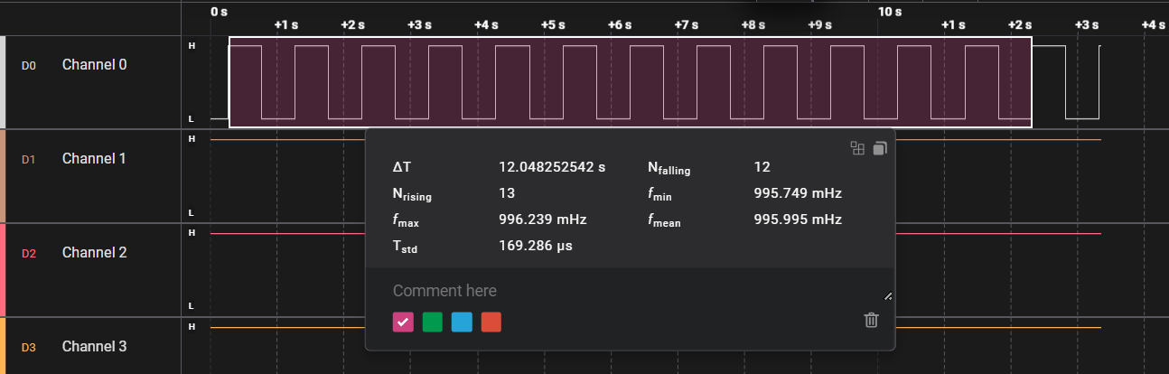
As seen from the screenshot, the blinky now runs much closer to 1Hz at 0.996Hz. So, basically it has improved by a large extent, but still a little bit slower with error of approximately 0.004Hz. This can be addressed by further reducing the delay value for counting, but it no longer remains an immediate load instruction, but becomes load from some location and hence results in 52 Bytes binary which clearly violates 50 bytes size constrain.
Let's try something different (completely different) ...
Since previous example of delay_blinky_10 doesn't allow further reduction in counter value without compromising the size constraint, is there a different way of counting to delay value ?
Let's say we need to count to 10 to achieve 1 second (1 Hz delay), then we will need to count to 5 to achieve 0.5 second delay. And at every 0.5 seconds, we will toggle LED, so that the final waveform becomes 1Hz. We can keep a freely incrementing counter variable (meaning that we will not reset it when reaching required delay value, rather we will let it keep on incrementing) and divide by 5. Upon doing this the division will return following values for different ranges of counter values :
| Counter | Counter / 5 | Odd / Even |
| 0-4 | 0 (0000) | Even |
| 5-9 | 1 (0001) | Odd |
| 10-14 | 2 (0010) | Even |
| 15-19 | 3 (0011) | Odd |
| 20-24 | 4 (0100) | Even |
| 25-29 | 5 (0101) | Odd |
| .... | ... | ... |
If you look carefully, the division by delay value (5) alternates between even and odd values at regular internal of 5 (delay value). Hence, the last bit of the division will keep on alternating among 0 (Even) and 1 (Odd). Using Bit-Band, it is the value of last bit that sets/resets the actual bit at given register address. Hence, we can store this division result in each iteration to achieve the delay, we just need to find out the number to divide the counter with. By trial and error, I found this value to be 727999.
Below is the pseudo-code for this method, and full source code can be found as delay_blinky_12 in github repo :
#define DELAY_VALUE     727999  // not a power of 2

__attribute__((naked)) int Reset_Handler(void)  {

    register uint32_t *RegToReadWrite = (uint32_t *)0x00000000;
    register uint32_t Counter = 1;
    register uint32_t Threshold = (uint32_t)DELAY_VALUE;

    // initialization omitted, RegToReadWrite holds
    // address of GPIOD ODR bit14 (PD14) in alias region.

    while (1)
    {
        // assign the result of division directly to ODR bit 14.
        *RegToReadWrite = (Counter / Threshold);

        // increment the Counter
        Counter++;
    }

    return 0;
}
When viewed with logic analyzer, it looks perfect 1Hz (actually rounded off by software till 3 digits after decimal point). Also it has binary size of 44 bytes. So it seems like this could be the perfect candidate for 1Hz challenge !!!???
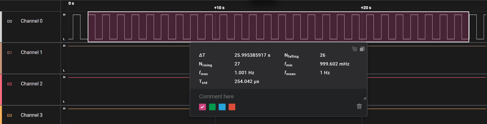
Never celebrate too early !
If a longer period capture (~60 seconds) is performed for delay_blinky_12, then it reveals a large variation of frequency (1 +/- 0.1Hz).
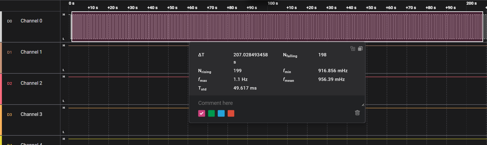
The program is logically correct, but there are two fundamental flaws with this method (division) :
- As per the ARM cortex M4 documentation, the division instruction takes variable amount of clock cycles (2 to 12) to execute, depending on values of input operands. Hence, the above variation of 0.1Hz can be assumed to be because of this.
- When counter overflows, the resultant waveform during that period can have discontinuous change in frequency, depending of remainder of counter with delay value.
Hence, this method produces unreliable and non-deterministic waveform around 1Hz. This method meets a dead end.
Taking a step back :)
After something new (delay_blinky_12) didn't work out as expected, I decided to improve upon existing stable code (delay_blinky_10). Somehow, it needs to allow counting to any arbitrary value and also constrain the size withing 50 bytes.
In delay_blinky_10, the counter was initialized with 1 and this value was used to initialize the peripheral registers by setting respective bits to 1 using bit-band. Now, using bit-band requires that 0th bit should be 0 or 1, whether the bit needs to be set or reset respectively. It doesn't matter what value other bits hold (0 or 1).
Hence, we can actually make use of this for our advantage like this :
- Not initializing the counter variable will reduce the size by 2 bytes (! yes, not initializing a local variable can be a bad practice, but it also helps reducing the code size and speeding up execution of given function where local variable is located - as long as code is compiled with optimization level 0).
- Initializing delay value with an odd number (found by trial and error) and using this value to initialize the peripheral register bits using bit-band. After all, it is the 0th bit value of an odd number that will set the respective bits. Note that this will increase the code size because this odd value won't result in immediate load and will be loaded from PC relative address. This fine as we have already reduced 2 bytes by not initializing the counter.
This example can be found as delay_blinky_13 in github repo.
// delay_blinky_10

#define DELAY_VALUE     2015232

__attribute__((naked)) int Reset_Handler(void)  {
    register uint32_t *RegToReadWrite = (uint32_t *)0x00000000;
    register uint32_t Counter = 1;
    register const uint32_t DelayValue = (uint32_t)DELAY_VALUE;
    ...
-------------------------------------------------------------

// delay_blinky_13

#define DELAY_VALUE     2002505  // not a power of 2, odd value

__attribute__((naked)) int Reset_Handler(void)  {
    register uint32_t *RegToReadWrite = (uint32_t *)0x00000000;
    register uint32_t Counter;      // no need to initialize Counter
    register uint32_t DelayValue = (uint32_t)DELAY_VALUE;
    ...
Enabling clock for GPIOD and setting PD14 as output :
// delay_blinky_10
*(PRPH_ALIAS_ADDR(AHB1ENR_ADDR, 3)) = Counter;
*(PRPH_ALIAS_ADDR(GPIOD_MODER_ADDR, 2 * LED_RED)) = Counter;
RegToReadWrite = PRPH_ALIAS_ADDR(GPIOD_ODR_ADDR, LED_RED);

-------------------------------------------------------------

// delay_blinky_13
*(PRPH_ALIAS_ADDR(AHB1ENR_ADDR, 3)) = DelayValue;
*(PRPH_ALIAS_ADDR(GPIOD_MODER_ADDR, 2 * LED_RED)) = DelayValue;
RegToReadWrite = PRPH_ALIAS_ADDR(GPIOD_ODR_ADDR, LED_RED);
the while loop will be same as before, except that counter is initialized with 0 instead of 1 but it doesn't make any difference :
// delay_blinky_10
while (1)
{
    Counter++;

    if (Counter >= DelayValue)
    {
        Counter = 1;
        *RegToReadWrite = ~(*RegToReadWrite);
    }
}

----------------------------------------------------

// delay_blinky_13
while (1)
{
    Counter++;

    if (Counter >= DelayValue)
    {
        Counter = 0;
        *RegToReadWrite = ~(*RegToReadWrite);
    }
}
Looking at the while loop, let's assess the impact of leaving Counter uninitialized. Counter is a register variable and general purpose registers can have any random value in them after MCU reset. There can be two possibilities :
- The value inside register represented by Counter is less than DelayValue. In this case the counter will increment till delay value and then reset to 0 while toggling the LED. Then onwards the counter will work normally.
- The value inside register represented by Counter is more than DelayValue. In this case the counter will immediately reset to 0 followed by toggling LED. Then onwards the counter will work normally.
In either of the cases, only the first cycle of the waveform will be affected, after that all the cycles will be normal. This is acceptable, as anyways it the first cycle only and we are not intending any time-critical hard real-time application.
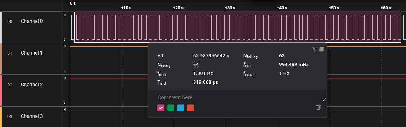
Looking it in logic analyzer, it reports average frequency of perfect 1Hz ! (truncated by software to 3 digits after decimal point, actually it is ~1.00019 Hz). Also, change in frequency is within 1 mHz, hence effectively generating a square wave of ~1 +/- 0.001 Hz with 50% duty cycle.
> make exesize
arm-none-eabi-size.exe obj/delay_blinky_13.elf
   text    data     bss     dec     hex filename
     48       0       0      48      30 obj/delay_blinky_13.elf
Compiling delay_blinky_13 yields same 48 bytes binary size similar to that of the previous examples, but now being much closer to 1Hz than before.
That's all.
In a nutshell, delay_blinky_13 has following features :
- Written completely in C, no usage of assembly language (not even inline assembly)
- Compiled binary size less than 50 bytes (48 bytes to be specific)
- Doesn't use RAM of MCU, instead all the variables are stored in general purpose registers of the cortex m4 core.
- No side effects, all the reads/writes for peripheral registers are performed atomically without affecting other bits in given registers, thanks to bit-band support.
- Deterministic code execution, no IRQs and all the instructions take same clock cycles to execute each time. Although there is one if block, but it executes only once and in sync with the toggling of the output pin.
- Closer to 1+/-0.001 Hz, although your stm32f4 may show a little bit different (because of clock accuracy difference) results and may vary significantly with temperature but that's because of RC HSI's accuracy. Also, the reference to measure (logic analyzer) is not much accurate (in my case).
Hexdump in QR code
for delay_blinky_13 :