 caspar
The main point of the inki devices it that you can hang them on the wall, no cables needed, and the (room) information is automatically retrieved and displayed on the epaper. For this, I want the circuit to run on conventional batteries as long as possible. However, the raspberry pico W board will consume a current in the mA range in its sleep mode, which effectively gives only a few days operating time. However, I would like to have operating time of years.
But, the board only needs to be active and online at certain times for a short duration when polling the server. For my application, typically about 15 seconds are needed, the online time is only about 3 seconds. More on this later (or on https://github.com/c0de111/inki). So let's build a circuit that is exploiting this!
To implement this application cycle and address the power consumption issue, I use a realtime clock DS3231 in combination with a simple p-mosfet Q1, see schematic. The basic ideas is as follows:
In the default state of the circuit, Q1 is in the off-state and the pico does not get any supply voltage. Two events can switch Q1 on via its gate and thus power the pico: An alarm from the RTC DS3231 via its INT pin, or a manual trigger via pushbutton #0. If this happens, the pico will start, and as a first action in its program pull down the gate from Q2, so that power is maintained even if the push button is released by the user. The pico will then execute its programme and always finish the programme with setting the next alarm in the DS3231, and, subsequently, finally cutting itself off power by switching Q1 off. Never forget to set the alarm, or you will never wake up again! This leaves the pico completely unpowered and the circuit back to the default state. In the default state, the circuits draws a few µA only, compared to several mA in the usual sleep modes of the pico. During the wake cycle, the current drawn is approximately 50 mA for about 15 seconds. The epaper is controlled via SPI, the DS3231 via I2C.

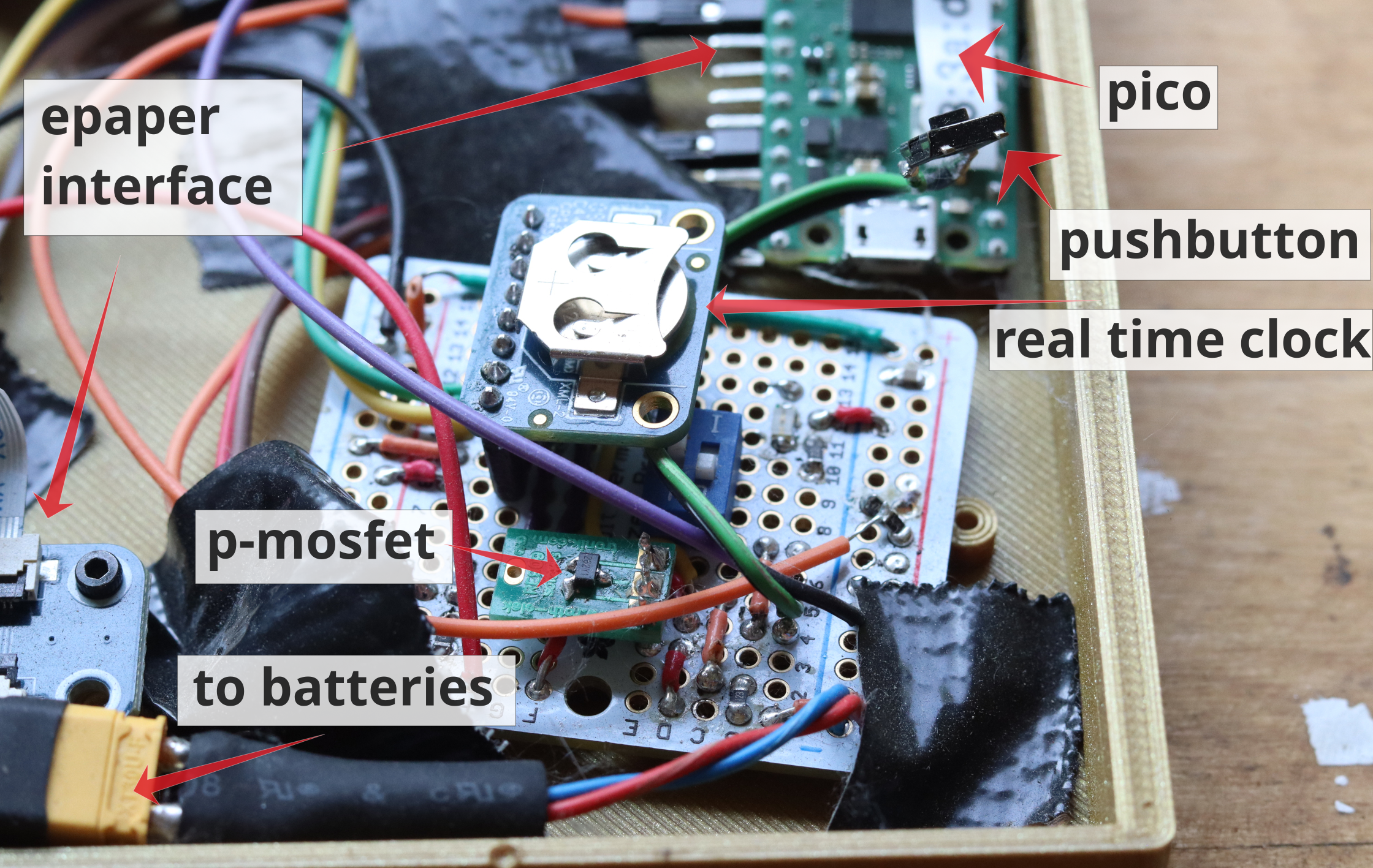
To test this approach I put together a prototype zero, see image at the start. Not exactly beautiful, and tedious to do, but it is good enough for testing and it has all the components (this is with the 7.5" epaper on the backside, not visible). The circuit did what I expected it to (after some mistakes, of course) - but how should I measure an expected current in the off-state in the range of µA? I do not really have a sufficiently sensitive current meter at home, and even if I had, not sure I would trust it ;).
Instead, to estimate the off-state current, I used the following approach: I now have a circuit that is powered on by the real time clock at programmable times and connecting to a server. The pico has an onboard analog-to-digital converter. So, I measure the battery voltage at each wake/refresh cycle, and log it on the server. Each refresh cycle will consume a certain amount of energy, while in the off-state the energy consumption is always present and constant. If I now change the refresh time, I can estimate the off-state current from the scaling, and compare to expectations. The figures below show two examples with a refresh time of two minutes, and 30 minutes, respectively. Note the different timescales of the plot (15 days vs. 198 days)! And, of course, I did not wait for 200 days ;) - this was just running along on its own.


In both cases, inki reaches about 10.000 refreshs, which means battery lifetime is not limited by power consumption in the off-state for these refresh times. Also, this agrees with expectations, see https://github.com/c0de111/inki for details. I use three simple & cheap supermarket AA alkaline batteries. The decay of the voltage seems to follow typical behavior (https://de.wikipedia.org/wiki/Alkali-Mangan-Zelle, chemistry going on!). Overall this means that lifetimes in the range of years are realistic, and also the circuit and firmware are very reliable (no error in 200 days and 10.000 cycles).
In the next log I will write about the firmware (which I also used for this part of the project).
Discussions
Become a Hackaday.io Member
Create an account to leave a comment. Already have an account? Log In.