Zappotron Super-Sequencer
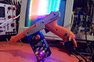
NES Zapper Controlled drum sequencer
NES Zapper Controlled drum sequencer
To make the experience fit your profile, pick a username and tell us what interests you.
We found and based on your interests.
Prices on some items were converted from Canadian dollars using 1 CAD = 0.75 USD
Read more »I couldn't find anything that matched the dimensions I needed so I built a case from scratch. I wanted the wooden box with metal faceplate look. My first stop was a scrap metal yard to get some sheet metal. I was really fortunate to find some panels with rectangles already cut out of them. They're 22.2cm wide, 36.6cm long, 1mm thick with inner rectangles 4.2cm by 5.5cm. My only metal cutting tool is a hacksaw which isn't capable of getting nice clean straight cuts like that. I can use the hacksaw to cut this down to smaller pieces and have nice straight lines because most of the cut is already there.
Next I went to a used building materials yard and got a 50cm x 100cm x 2cm "shelving board". I think it's made out of pine.
I did some rough sketches and chose the most aesthetic one. I was constrained by needing to fit the bulky cathode ray tube; the sizes I could easily cut the metal panel to; and the amount of wood I had to work with.
This is the plan for the side panel. It's based on the bottom left concept sketch. Length of each side was chosen to match what the metal panels could be easily cut to.
I used a jigsaw to cut out the side panels.
This is me cutting out a section of metal panel to provide an opening for one of the tape drives.
Metal panels cut.
The case starting to take shape.
I didn't have enough wood left to make the base a single solid piece so it consists of four separate pieces glued together. The battery holder is built into the base.
I used a hole saw and drill to make a hole for the TV speaker. Also in this picture you can see a screw and washer in the bottom left that forms a hinge holding the base and sides together. This lets the case open very easily. I want it to be easy to get at the circuit boards and batteries.
Here it is with the stain and varnish applied. I went to a paint recycling centre and bought an almost empty can of "Minwax red mahogany 2-in one stain and varnish". I also added a cabinet handle from the scrap metal yard to make it easier to carry. I really like the utilitarian look of equipment with a carrying handle.
I didn't want the batteries to come out of their holder while the unit was closed and being carried around. They could potentially hit the fragile glass at the back of the CRT. I added a piece of wood and foam pad to land on top of the batteries when the case was closed. The foam was part of the packaging from an order of electronic components. I made sure it wasn't the conductive foam used to protect chips from static. That would gradually drain the batteries.
This is the case closed with the batteries securely held in place.
Finally I used a couple random bits of metal from the scrap metal yard to build a holder for the zapper. Now I can carry the project with one hand.
This is a view of the case opened. The empty section in the top left is where the back of the CRT ends up when the case closes.
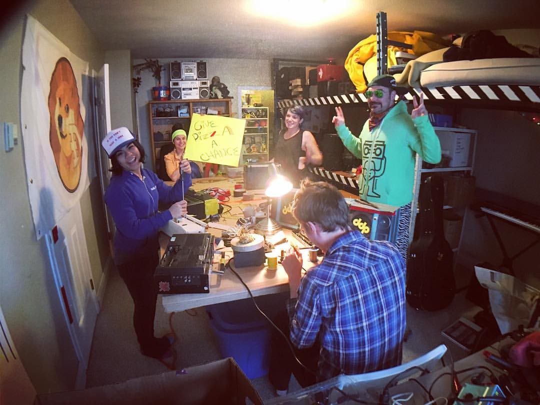
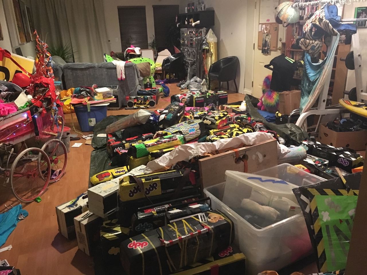
I help out a group of people who collect hundreds of boomboxes and use them to throw free public dance parties. I'm responsible for electronic repairs to keep the boomboxes alive. My success rate is very high but some are completely beyond saving. I salvaged the tape decks from a pair of these. I'm counting them as free on the parts list.
Some pictures from a repair day.
One of the salvaged tape drives.
The tape drive mechanisms had some flywheels (heavy metal disks) to provide inertia which stabilizes the rotation speed of the spindles. That's the opposite of what I want so I removed them. This lets the tape speed change with each drum step a lot faster.
The tape drives mounted in the case. I need the control buttons to be accessible because tapes are locked in place while the play button is down and I want to be able to change tapes.
The motors are run with current boost transistors on the audio control output opamps. A tape deck needs a circuit to amplify the signal from the magnetic tape head. I salvaged the boards for this from the boomboxes and Identified the audio output points. Those run to the mixer.
My circuit could make one of the tape deck motors run at normal speed and even a little faster. The other tape deck ran much slower. With the control voltage at 100% it's only going about 40% of normal speed. I believe that motor was intended to run at 12v while the "good" one was meant to run at 4.5v. I could have changed the control voltage circuit to give a 0-9v output or replaced the motor on the slow deck; but I found myself really enjoying the noises it was making. It makes a very deep muffled type of sound; like listening to a heartbeat through a stethescope.
The tapes themselves were either left in boomboxes when they were donated or found in various garbage piles.
I've always loved the sounds of the TI SP0256 allaphone chip and was hoping to find something using it for this project. That's chip is what gave the speak-and-spell its robot voice. I picked up a "VTECH Talking LITTLE SMART alphabet DESK" at a garage sale because my ears could tell it was using a TI allophone chip.
I opened it up and found the PCB didn't contain an SP0256. There were only two chips. One was a 74HC138 (3-8 line decoder) which was part of the matrix circuit used to read all those buttons. The other chip must therefore be a microcontroller speech synthesizer combo.
I googled the marking on the chip and wasn't able to find any datasheets so I had to dig deeper. I know the toy was made in 1995; what the chip does; and that TI made it. This is enough information to conclude it's actually a TSP50C11. TI is good enough to keep datasheets of 25 year old obsolete chips on their website. Circuit bending gets a lot easier when you can read a datasheet instead of randomly poking things.
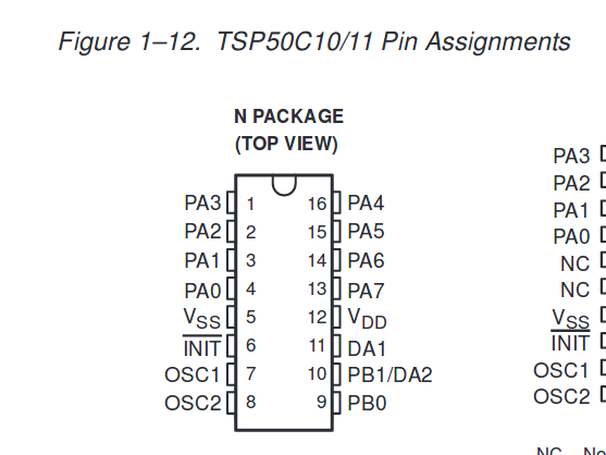
The first thing I wanted to do was control how fast the chip spoke by attaching a CD4046 voltage controlled oscillator to it's clock input (OSC1). The original circuit board was using an LC oscillator to drive the clock. I cut that from both OSC1 and OSC2, left OSC2 floating, and ran the CD4046 output to OSC1.
It worked OK, but not quiet perfect. The original oscillator had been running at 1.6MHz, but a CD4046 has a top speed of 1.0 MHz when powered with 5v. This meant even with the control voltage at 100% the toy was speaking in a slowed down voice.
The CD4046 is frequently used in synthesizers because of its robust VCO, but it's intended application was FM/FSK demodulation. It contains three different phase comparators meant for this. One of these phase comparators is a XOR gate. XOR gates can be used as clock doublers. By doubling the VCO frequency through the XOR gate I can get up to the 1.6MHz required for normal sound speed. A clock doubler works by detecting both the rising and falling edge of an input.
I could push the clock past 1.6MHz, but that made the TSP50C11
act erratically then become unresponsive until power cycled, so I chose
not to do that.
There was some unexpected behaviour from the TSP50C11 INIT pin. It needs to be high for the chip to run; but I couldn't just tie it to VCC. It needs to be low on power up then brought high afterwords. I connect it to a capacitor that's charging up slowly through a large resistor to get this behaviour. The original toy used two switches to do this, but that's clunky.
Here you can see the wires I've soldered to the TSP50C11.
Yellow: Init(6)
Orange: OSC1(7)
Purple: DA1(11). This is the audio output pin that runs to the mixer.
The PCB has been cut on the bottom side to remove OSC1 and OSC2 from the original LC oscillator.
Ground and 5v are connected through the wires that originally went from the PCB to the battery pack.
I didn't want the huge panel of buttons on the project, so I analyzed how the button matrix was wired and soldered in a rotary switch that lets me select one of the six buttons from the top row, The toy has several modes such as asking you to spell a word or solve arithmetic problems, but I only wanted it to be in one of two modes: Say the letter or make the animal noise. The top row of buttons have both an animal and letter next to them.
Finally I needed to trigger the sound to start playing on each transition of the drum step count or the drum step count resetting to 0. With the second option it starts playing a sound when the drum step is at 0 and varies its pitch with the control voltage set at each step. The following pictures shows where the connections had to be made.
There were also four 2N3904 transistors that needed to be removed. Their silkscreen is visible in the bottom right. These formed an H-bridge to drive the toy's speaker. My bending had caused a problem where both sides of the H-bridge were closed at the same time; resulting in a path from Vcc to ground with only a...
Read more »Now that the control voltages are working I need something to control. A vary popular chip for electronic music hobyists is the CD4046 voltage controlled phase locked loop oscillator. It generates a 50% duty cycle square wave controlled by the VCO input voltage and with max and min frequencies set by two resistors and a capacitor.
I hooked up the standard circuit and it worked; but I didn't like the sound. It was too simple and clean. It was the kind of simple beeps I'd expect from a microwave or a printer that wants more paper. Purely by accident I discovered that disconnecting the Vcc pin from 5v produced a much more interesting dirty sound. I'd have never thought to try that deliberately. Shouldn't the chip just be off if it's not getting any power? I'm assuming it's drawing power from the VCO control input because there isn't anywhere else it could come from.
I was hoping that all four of the audio generating circuits would shut off when the control voltage was almost at 0v (dot moved to the left of the screen). This is low enough that the tape motors stop turning and the 4046s stop oscillating. Unfortunetely the audio circuits all produced noticable static in this state.
This circuit solves that problem. I feed the control voltage for each of the audio circuits into an LM339 which compares them to 0.5v. When a control voltage is below 0.5v a 4066 analog switch is opened which cuts off the returning audio before reaching the mixer.
The mixer itself is a simple passive design consisting of 100k logarithmic potentiometers and capacitors for AC coupling. Volume control should use logarithmic potentiometers because the human perception of sound volume is approximately logarithmic,
The mixer potentiometers line up with the control button for their respective channel.
The drum step counter is slowly counting from 0-15. I need to get the voltages out of the capacitor demultiplexers that match this index so they can control audio generating circuits. The problem is the capacitor demultiplexers is already being addressed by the draw step count which cycles from 0-15 sixty times a second. I can't change this without losing the indication dots on the TV.
The solution is to take advantage of the 74LS85 output used to produce an indication bar and add a set of sample-and-hold circuits. One of the 16 steps being drawn on the screen matches the drum step count. If I only allow a capacitor to charge from the demultiplexer output during this period it will take the voltage of the capacitor in the demultiplexer that matches the drum step count.
I'm adding the control to run the tape drive motors at this point too. Outputs destined for motors are voltage followers with a 2N3904 current boost. Outputs going to 4046 VCOs are regular opamp buffers. An LM324 audio op-amp is used here because it doesn't need to handle a high frequency video rate signal.
So far I've covered three circuits with outputs to the TV: The position dot window circuit; the highlighting window circuit; and the 74ls85 output that highlights the step the drum sequencer is presently on. I'm adding a fourth video output at this point: a set of sixteen dark lines that divide each step. With this dark line it's easier to differentiate the individual channels within each step.
The separator line is done by running channel draw select 2 through a capacitor. This creates an edge detector that responds to the transition it makes when the channel draw count resets.
The four signals are mixed with a simple transistor circuit. It produces a light grey by default. Inputs to the collector bump up the brightness. Inputs to the base bump down the brightness. The highlight and drum step indicator are drawn as white. The separator line and position dots are drawn as darker grey.
This is the circuit that lets the drum sequencer skip over selected steps. Without this every tune would have to be sixteen steps long. It is controlled with the zapper and another pair of buttons. When the delete button is pressed the step being pointed at by the zapper is set to be skipped over. When the insert button is pressed the step pointed at by the zapper is no longer set to be skipped.
The circuit uses a pair of 74HC164 shift registers to form a 16bit
circular buffer. Channel draw select 2 comes from the same binary count
as the four bits that select which step is being drawn, but one bit
lower. This means using it to clock the pair of 164s makes them cycle through all 16 bits as the 16 steps are being drawn to the screen.
A point is pulled to either 5v or ground by pressing the insert or delete button. There's a 270Ω
resistor between the insert button and ground so there won't be a
short if both buttons are pressed at once. When the zapper picks up the
raster beam being drawn it charges up a capacitor through a diode.
This capacitor then discharges slowly producing a signal that remains
high for several scanlines after the zapper detection. This signal
closes a 4066 that lets the new value set by the buttons into the
circular buffer. The new value needs to be present as the shift
registers are making a transition which is why it was necessary to
stretch out the zapper pulse.
Skip draw signal is an output to the TV which brightens lines that have been set to be skipped over. Skipper is a signal that goes to the drum step count 4040. It makes the counter increment again right away if the present step is set to be skipped over. This works by ANDing the skip draw signal with the 74LS85 output. If both of these signals are high at the same time the drum sequence count must be on a line that's set to be skipped over.
The 4066 responsible for this circuit is the same one used for video porching and the zapper sampled sawtooth.
A 4040 binary counter keeps track of where the drum sequence is. It's clocked by a 555 astable circuit with a variable frequency set by a potentiometer. This changes the tempo of the drum machine. The output of this binary counter is compared to the display count using a 74LS85 4-bit binary magnitude comparator. The 74LS85 produces a 1 only when the two sets of input bits match. When this runs back to the screen it produces a line that highlights where the drum sequence is because the 74LS85 will only output high when those scanlines are being drawn. The signal also triggers four sample-and-hold circuits that copy the values stored in capacitors indicated by the drum count.
The 74LS85 has inputs labelled "A=B IN", A>B IN", "A<B IN". These allow two or more 74LS85s to be cascaded to compare larger binary numbers. For this application A>B and A<B should be at ground and A=B at Vcc.
The 555 runs to the 4040 clock through a diode which forms an OR gate with another diode. The drum sequencer skips over selected steps by sending a second "skipper" pulse to the 4040 through this gate.
Create an account to leave a comment. Already have an account? Log In.
Become a member to follow this project and never miss any updates
 tobi tubbutec
 Russell Kramer
 MaBe42