This project is built for the Moog Circuit Bending Challenge. The important rules are a budget of $70 and everything needs to be battery powered not exceeding 9v.
My circuits will work with any NTSC CRT television, but one that plugs into the wall would violate the 9v rule. I went to a flea market and was able to find a 19cm x 14cm Citizen Portable. I haggled it down to $5 CAD because it's black and white and doesn't work due to an issue I'll get to later.
This was a real stroke of luck since portable CRTs are almost always half that size. A larger screen makes using the light gun a lot easier. I spent the entire project terrified I'd crack the tube and be completely unable to find a replacement.
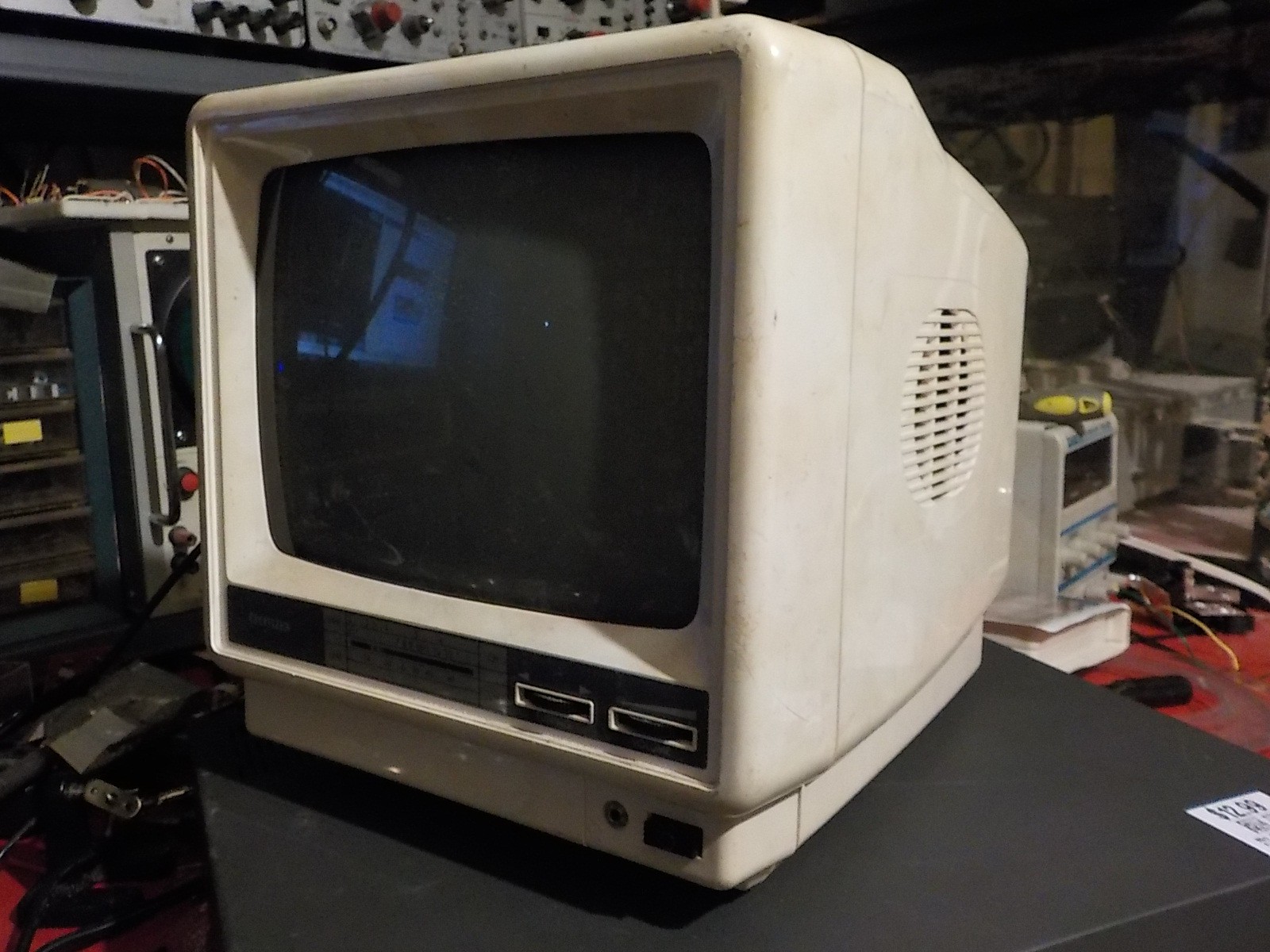
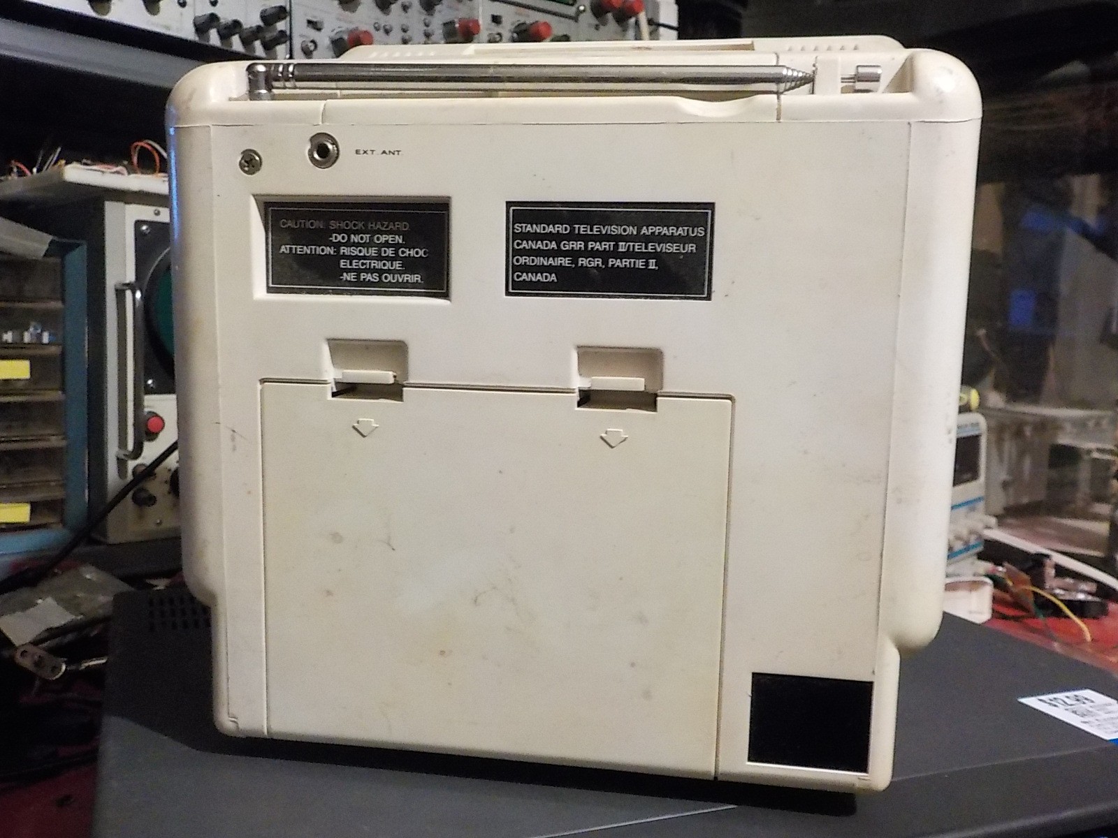
The issue with the TV: The only input source is an antenna. It has no coax or composite jack. The jack on the front is a 3.5mm headphone out. This TV has been a paperweight since analog broadcasts were shut down a few years ago.
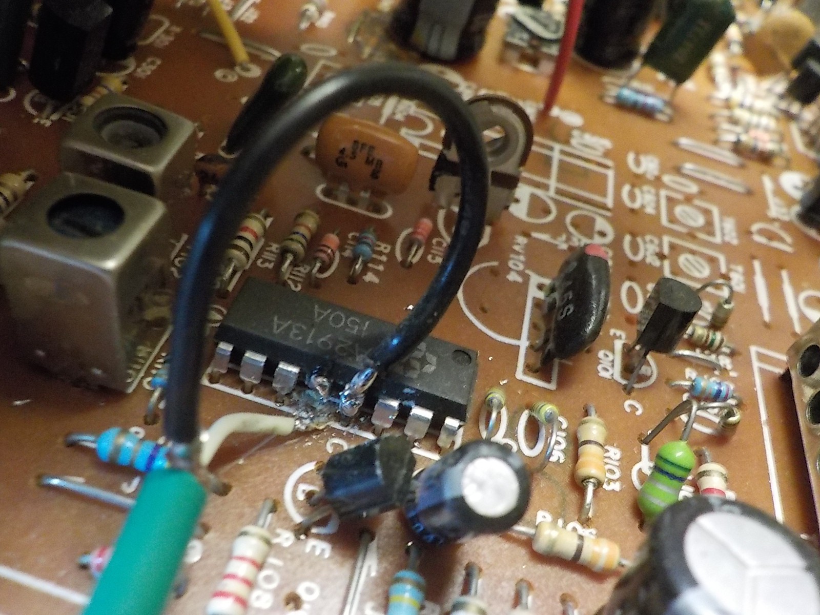
I know North American analog TV broadcasts were NTSC modulated with an RF carrier wave, so inside the TV I should find an RF demodulator that outputs NTSC. The challenge is to figure out where that point is so I can cut out the demodulator and splice in a wired NTSC signal. I also want to take advantage of the TV's amplifier and speaker by adding an audio input.
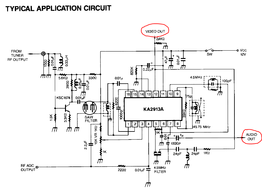
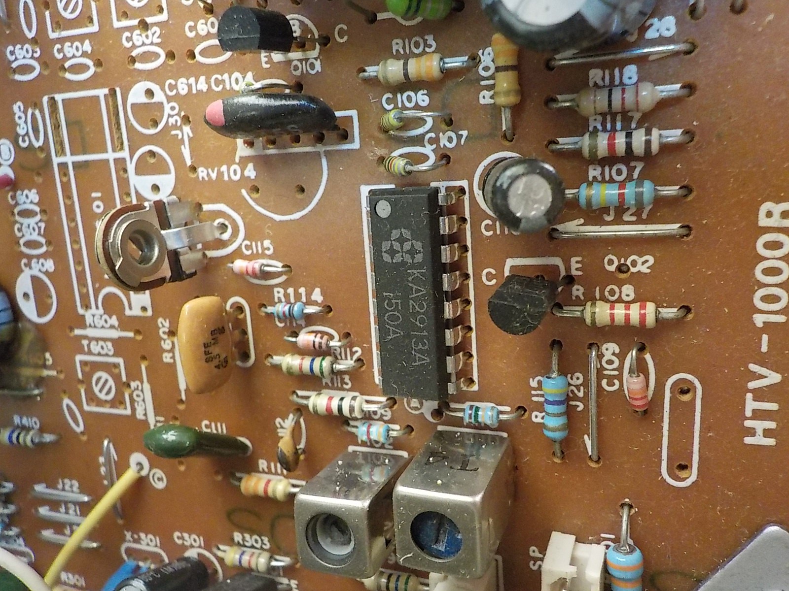
I looked at the PCB and saw variable inductors that were likely part of the antenna tuner. Above them is a KA2913A chip. A google search brought up a datasheet which told me this is a chip designed for TV demodulation and which pins contain the video and audio outputs. It's usually not this easy to get a datasheet for chips out of random electronics. My backup plan was to first identify the high voltage points on the PCB then poke the safe areas with the output from a VCR until I got an image.
Now the TV can play a wired NTSC video signal. It's connected to a VCR in this picture.

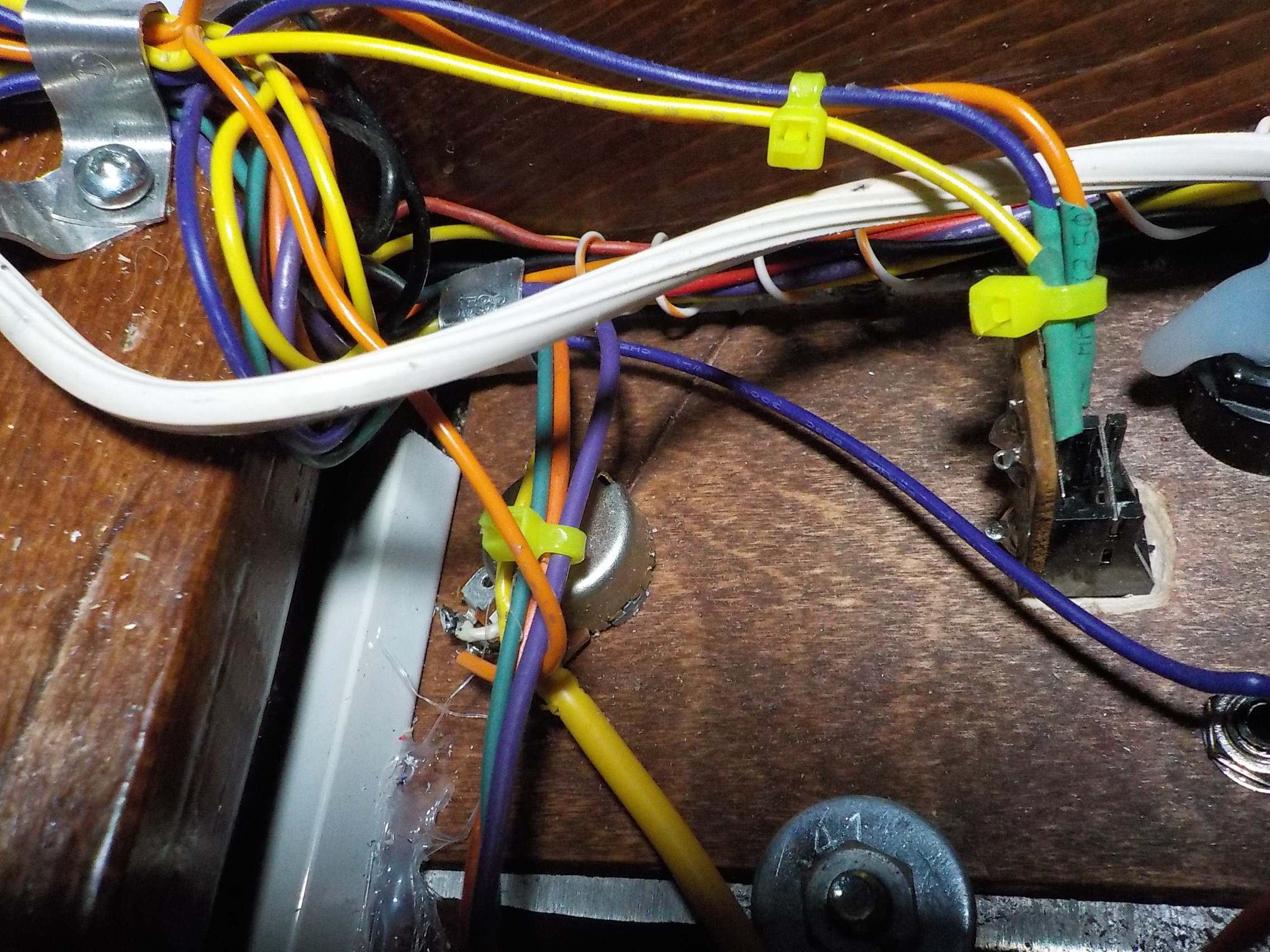
I found the demodulated audio point connected to the volume control potentiometer which was a much more convenient place to splice in a wire than the PCB. Creating an audio input to the TV lets me use the speaker, speaker driver, headphone jack, and volume potentiometer that were already part of it. The speaker sounded a lot better after being mounted to a wooden case.
Volume potentiometer on the left. Headphone jack on the right.
 Russell Kramer
Discussions
Become a Hackaday.io Member
Create an account to leave a comment. Already have an account? Log In.